Vol. 3C 24-9
VIRTUAL MACHINE CONTROL STRUCTURES
All other bits in this field are reserved, some to 0 and some to 1. Software should consult the VMX capability MSRs
IA32_VMX_PINBASED_CTLS and IA32_VMX_TRUE_PINBASED_CTLS (see Appendix A.3.1) to determine how to
set reserved bits. Failure to set reserved bits properly causes subsequent VM entries to fail (see Section 26.2.1.1).
The first processors to support the virtual-machine extensions supported only the 1-settings of bits 1, 2, and 4.
The VMX capability MSR IA32_VMX_PINBASED_CTLS will always report that these bits must be 1. Logical proces-
sors that support the 0-settings of any of these bits will support the VMX capability MSR
IA32_VMX_TRUE_PINBASED_CTLS MSR, and software should consult this MSR to discover support for the 0-
settings of these bits. Software that is not aware of the functionality of any one of these bits should set that bit to 1.
24.6.2 Processor-Based
VM-Execution Controls
The processor-based VM-execution controls constitute two 32-bit vectors that govern the handling of synchronous
events, mainly those caused by the execution of specific instructions.
1
These are the primary processor-based
VM-execution controls and the secondary processor-based VM-execution controls.
Table 24-6 lists the primary processor-based VM-execution controls. See Chapter 25 for more details of how these
controls affect processor behavior in VMX non-root operation.
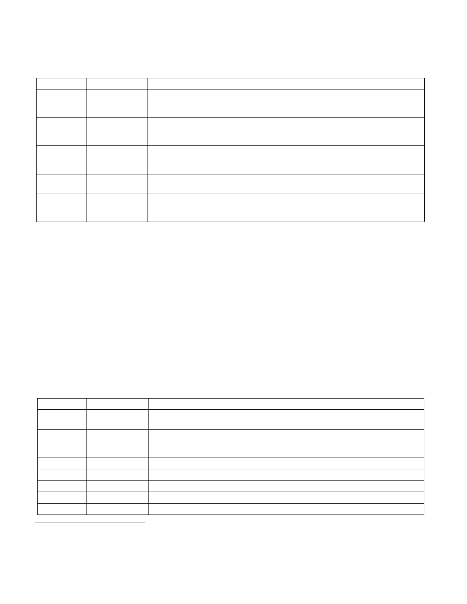
Table 24-5. Definitions of Pin-Based VM-Execution Controls
Bit Position(s) Name
Description
0
External-interrupt
exiting
If this control is 1, external interrupts cause VM exits. Otherwise, they are delivered normally
through the guest interrupt-descriptor table (IDT). If this control is 1, the value of RFLAGS.IF
does not affect interrupt blocking.
3
NMI exiting
If this control is 1, non-maskable interrupts (NMIs) cause VM exits. Otherwise, they are
delivered normally using descriptor 2 of the IDT. This control also determines interactions
between IRET and blocking by NMI (see Section 25.3).
5
Virtual NMIs
If this control is 1, NMIs are never blocked and the “blocking by NMI” bit (bit 3) in the
interruptibility-state field indicates “virtual-NMI blocking” (see Table 24-3). This control also
interacts with the “NMI-window exiting” VM-execution control (see Section 24.6.2).
6
Activate VMX-
preemption timer
If this control is 1, the VMX-preemption timer counts down in VMX non-root operation; see
Section 25.5.1. A VM exit occurs when the timer counts down to zero; see Section 25.2.
7
Process posted
interrupts
If this control is 1, the processor treats interrupts with the posted-interrupt notification vector
(see Section 24.6.8) specially, updating the virtual-APIC page with posted-interrupt requests
(see Section 29.6).
1. Some instructions cause VM exits regardless of the settings of the processor-based VM-execution controls (see Section 25.1.2), as
do task switches (see Section 25.2).
Table 24-6. Definitions of Primary Processor-Based VM-Execution Controls
Bit Position(s) Name
Description
2
Interrupt-window
exiting
If this control is 1, a VM exit occurs at the beginning of any instruction if RFLAGS.IF = 1 and
there are no other blocking of interrupts (see Section 24.4.2).
3
Use TSC offsetting This control determines whether executions of RDTSC, executions of RDTSCP, and executions
of RDMSR that read from the IA32_TIME_STAMP_COUNTER MSR return a value modified by
the TSC offset field (see Section 24.6.5 and Section 25.3).
7
HLT exiting
This control determines whether executions of HLT cause VM exits.
9
INVLPG exiting
This determines whether executions of INVLPG cause VM exits.
10
MWAIT exiting
This control determines whether executions of MWAIT cause VM exits.
11
RDPMC exiting
This control determines whether executions of RDPMC cause VM exits.
12
RDTSC exiting
This control determines whether executions of RDTSC and RDTSCP cause VM exits.