Vol. 3C 24-5
VIRTUAL MACHINE CONTROL STRUCTURES
The base address, segment limit, and access rights compose the “hidden” part (or “descriptor cache”) of each
segment register. These data are included in the VMCS because it is possible for a segment register’s descriptor
cache to be inconsistent with the segment descriptor in memory (in the GDT or the LDT) referenced by the
segment register’s selector.
The value of the DPL field for SS is always equal to the logical processor’s current privilege level (CPL).
1
•
The following fields for each of the registers GDTR and IDTR:
— Base address (64 bits; 32 bits on processors that do not support Intel 64 architecture).
— Limit (32 bits). The limit fields contain 32 bits even though these fields are specified as only 16 bits in the
architecture.
•
The following MSRs:
— IA32_DEBUGCTL (64 bits)
— IA32_SYSENTER_CS (32 bits)
— IA32_SYSENTER_ESP and IA32_SYSENTER_EIP (64 bits; 32 bits on processors that do not support Intel 64
architecture)
— IA32_PERF_GLOBAL_CTRL (64 bits). This field is supported only on processors that support the 1-setting
of the “load IA32_PERF_GLOBAL_CTRL” VM-entry control.
— IA32_PAT (64 bits). This field is supported only on processors that support either the 1-setting of the “load
IA32_PAT” VM-entry control or that of the “save IA32_PAT” VM-exit control.
— IA32_EFER (64 bits). This field is supported only on processors that support either the 1-setting of the “load
IA32_EFER” VM-entry control or that of the “save IA32_EFER” VM-exit control.
— IA32_BNDCFGS (64 bits). This field is supported only on processors that support either the 1-setting of the
“load IA32_BNDCFGS” VM-entry control or that of the “clear IA32_BNDCFGS” VM-exit control.
•
The register SMBASE (32 bits). This register contains the base address of the logical processor’s SMRAM image.
24.4.2
Guest Non-Register State
In addition to the register state described in Section 24.4.1, the guest-state area includes the following fields that
characterize guest state but which do not correspond to processor registers:
•
Activity state (32 bits). This field identifies the logical processor’s activity state. When a logical processor is
executing instructions normally, it is in the active state. Execution of certain instructions and the occurrence
of certain events may cause a logical processor to transition to an inactive state in which it ceases to execute
instructions.
The following activity states are defined:
2
— 0: Active. The logical processor is executing instructions normally.
13
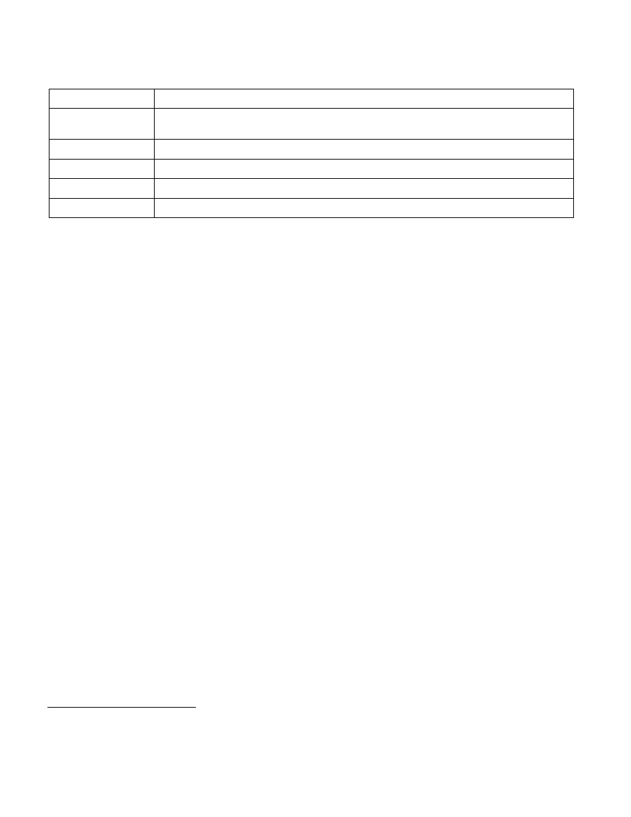
Reserved (except for CS)
L — 64-bit mode active (for CS only)
14
D/B — Default operation size (0 = 16-bit segment; 1 = 32-bit segment)
15
G — Granularity
16
Segment unusable (0 = usable; 1 = unusable)
31:17
Reserved
1. In protected mode, CPL is also associated with the RPL field in the CS selector. However, the RPL fields are not meaningful in real-
address mode or in virtual-8086 mode.
Table 24-2. Format of Access Rights (Contd.)
Bit Position(s)
Field