24-18 Vol. 3C
VIRTUAL MACHINE CONTROL STRUCTURES
All other bits in this field are reserved, some to 0 and some to 1. Software should consult the VMX capability MSRs
IA32_VMX_EXIT_CTLS and IA32_VMX_TRUE_EXIT_CTLS (see Appendix A.4) to determine how it should set the
reserved bits. Failure to set reserved bits properly causes subsequent VM entries to fail (see Section 26.2.1.2).
The first processors to support the virtual-machine extensions supported only the 1-settings of bits 0–8, 10, 11,
13, 14, 16, and 17. The VMX capability MSR IA32_VMX_EXIT_CTLS always reports that these bits must be 1.
Logical processors that support the 0-settings of any of these bits will support the VMX capability MSR
IA32_VMX_TRUE_EXIT_CTLS MSR, and software should consult this MSR to discover support for the 0-settings of
these bits. Software that is not aware of the functionality of any one of these bits should set that bit to 1.
24.7.2
VM-Exit Controls for MSRs
A VMM may specify lists of MSRs to be stored and loaded on VM exits. The following VM-exit control fields deter-
mine how MSRs are stored on VM exits:
•
VM-exit MSR-store count (32 bits). This field specifies the number of MSRs to be stored on VM exit. It is
recommended that this count not exceed 512 bytes.
1
Otherwise, unpredictable processor behavior (including a
machine check) may result during VM exit.
•
VM-exit MSR-store address (64 bits). This field contains the physical address of the VM-exit MSR-store area.
The area is a table of entries, 16 bytes per entry, where the number of entries is given by the VM-exit MSR-store
count. The format of each entry is given in Table 24-11. If the VM-exit MSR-store count is not zero, the address
must be 16-byte aligned.
See Section 27.4 for how this area is used on VM exits.
The following VM-exit control fields determine how MSRs are loaded on VM exits:
•
VM-exit MSR-load count (32 bits). This field contains the number of MSRs to be loaded on VM exit. It is
recommended that this count not exceed 512 bytes. Otherwise, unpredictable processor behavior (including a
machine check) may result during VM exit.
2
•
VM-exit MSR-load address (64 bits). This field contains the physical address of the VM-exit MSR-load area.
The area is a table of entries, 16 bytes per entry, where the number of entries is given by the VM-exit MSR-load
count (see Table 24-11). If the VM-exit MSR-load count is not zero, the address must be 16-byte aligned.
See Section 27.6 for how this area is used on VM exits.
24.8 VM-ENTRY
CONTROL
FIELDS
The VM-entry control fields govern the behavior of VM entries. They are discussed in Sections 24.8.1 through
24.8.3.
NOTES:
1. Since Intel 64 architecture specifies that IA32_EFER.LMA is always set to the logical-AND of CR0.PG and IA32_EFER.LME, and since
CR0.PG is always 1 in VMX operation, IA32_EFER.LMA is always identical to IA32_EFER.LME in VMX operation.
1. Future implementations may allow more MSRs to be stored reliably. Software should consult the VMX capability MSR
IA32_VMX_MISC to determine the number supported (see Appendix A.6).
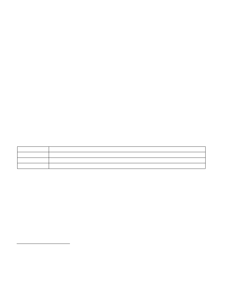
Table 24-11. Format of an MSR Entry
Bit Position(s)
Contents
31:0
MSR index
63:32
Reserved
127:64
MSR data
2. Future implementations may allow more MSRs to be loaded reliably. Software should consult the VMX capability MSR
IA32_VMX_MISC to determine the number supported (see Appendix A.6).