Vol. 3C 24-19
VIRTUAL MACHINE CONTROL STRUCTURES
24.8.1 VM-Entry
Controls
The VM-entry controls constitute a 32-bit vector that governs the basic operation of VM entries. Table 24-12 lists
the controls supported. See Chapter 24 for how these controls affect VM entries.
All other bits in this field are reserved, some to 0 and some to 1. Software should consult the VMX capability MSRs
IA32_VMX_ENTRY_CTLS and IA32_VMX_TRUE_ENTRY_CTLS (see Appendix A.5) to determine how it should set
the reserved bits. Failure to set reserved bits properly causes subsequent VM entries to fail (see Section 26.2.1.3).
The first processors to support the virtual-machine extensions supported only the 1-settings of bits 0–8 and 12.
The VMX capability MSR IA32_VMX_ENTRY_CTLS always reports that these bits must be 1. Logical processors that
support the 0-settings of any of these bits will support the VMX capability MSR IA32_VMX_TRUE_ENTRY_CTLS
MSR, and software should consult this MSR to discover support for the 0-settings of these bits. Software that is not
aware of the functionality of any one of these bits should set that bit to 1.
24.8.2
VM-Entry Controls for MSRs
A VMM may specify a list of MSRs to be loaded on VM entries. The following VM-entry control fields manage this
functionality:
•
VM-entry MSR-load count (32 bits). This field contains the number of MSRs to be loaded on VM entry. It is
recommended that this count not exceed 512 bytes. Otherwise, unpredictable processor behavior (including a
machine check) may result during VM entry.
1
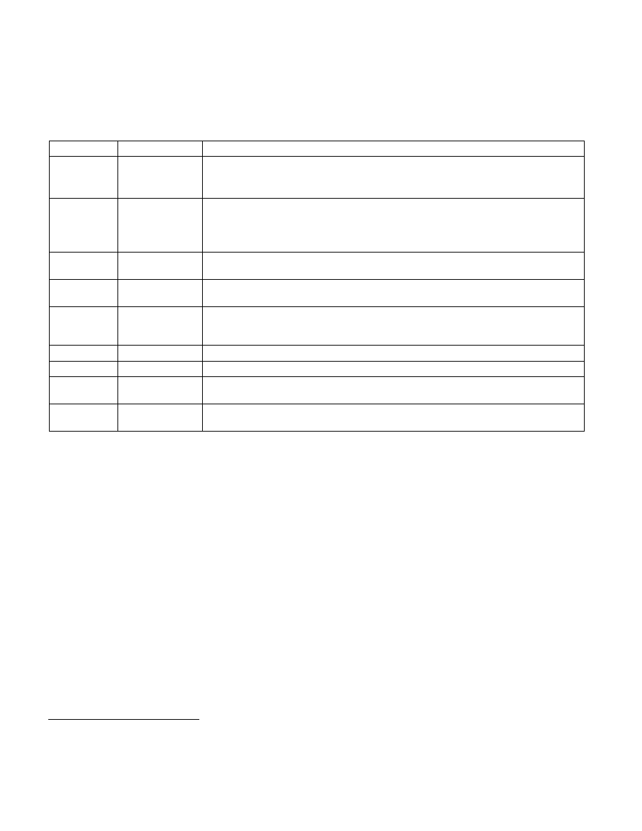
Table 24-12. Definitions of VM-Entry Controls
Bit Position(s) Name
Description
2
Load debug
controls
This control determines whether DR7 and the IA32_DEBUGCTL MSR are loaded on VM entry.
The first processors to support the virtual-machine extensions supported only the 1-setting of
this control.
9
IA-32e mode guest On processors that support Intel 64 architecture, this control determines whether the logical
processor is in IA-32e mode after VM entry. Its value is loaded into IA32_EFER.LMA as part of
VM entry.
1
This control must be 0 on processors that do not support Intel 64 architecture.
NOTES:
1. Bit 5 of the IA32_VMX_MISC MSR is read as 1 on any logical processor that supports the 1-setting of the “unrestricted guest” VM-
execution control. If it is read as 1, every VM exit stores the value of IA32_EFER.LMA into the “IA-32e mode guest” VM-entry control
(see Section 27.2).
10
Entry to SMM
This control determines whether the logical processor is in system-management mode (SMM)
after VM entry. This control must be 0 for any VM entry from outside SMM.
11
Deactivate dual-
monitor treatment
If set to 1, the default treatment of SMIs and SMM is in effect after the VM entry (see Section
34.15.7). This control must be 0 for any VM entry from outside SMM.
13
Load
IA32_PERF_GLOBA
L_CTRL
This control determines whether the IA32_PERF_GLOBAL_CTRL MSR is loaded on VM entry.
14
Load IA32_PAT
This control determines whether the IA32_PAT MSR is loaded on VM entry.
15
Load IA32_EFER
This control determines whether the IA32_EFER MSR is loaded on VM entry.
16
Load
IA32_BNDCFGS
This control determines whether the IA32_BNDCFGS MSR is loaded on VM entry.
17
Conceal VM entries
from Intel PT
If this control is 1, Intel Processor Trace does not produce a paging information packet (PIP) on
a VM entry (see Chapter 36).
1. Future implementations may allow more MSRs to be loaded reliably. Software should consult the VMX capability MSR
IA32_VMX_MISC to determine the number supported (see Appendix A.6).