17-34 Vol. 3B
DEBUG, BRANCH PROFILE, TSC, AND RESOURCE MONITORING FEATURES
•
BTS (branch trace store) flag (bit 3) — When set, enables the BTS facilities to log BTMs to a memory-
resident BTS buffer that is part of the DS save area. See Section 17.4.9, “BTS and DS Save Area.”
•
BTINT (branch trace interrupt) flag (bits 4) — When set, the BTS facilities generate an interrupt when the
BTS buffer is full. When clear, BTMs are logged to the BTS buffer in a circular fashion. See Section 17.4.5, “Branch
Trace Store (BTS).”
•
BTS_OFF_OS (disable ring 0 branch trace store) flag (bit 5) — When set, enables the BTS facilities to
skip sending/logging CPL_0 BTMs to the memory-resident BTS buffer. See Section 17.11.2, “LBR Stack for
Processors Based on Intel NetBurst® Microarchitecture.”
•
BTS_OFF_USR (disable ring 0 branch trace store) flag (bit 6) — When set, enables the BTS facilities to
skip sending/logging non-CPL_0 BTMs to the memory-resident BTS buffer. See Section 17.11.2, “LBR Stack for
Processors Based on Intel NetBurst® Microarchitecture.”
NOTE
The initial implementation of BTS_OFF_USR and BTS_OFF_OS in MSR_DEBUGCTLA is shown in
Figure 17-12. The BTS_OFF_USR and BTS_OFF_OS fields may be implemented on other model-
specific debug control register at different locations.
See Chapter 35, “Model-Specific Registers (MSRs),” for a detailed description of each of the last branch recording
MSRs.
17.11.2 LBR Stack for Processors Based on Intel NetBurst® Microarchitecture
The LBR stack is made up of LBR MSRs that are treated by the processor as a circular stack. The TOS pointer
(MSR_LASTBRANCH_TOS MSR) points to the LBR MSR (or LBR MSR pair) that contains the most recent (last)
branch record placed on the stack. Prior to placing a new branch record on the stack, the TOS is incremented by 1.
When the TOS pointer reaches it maximum value, it wraps around to 0. See Table 17-18 and Figure 17-12.
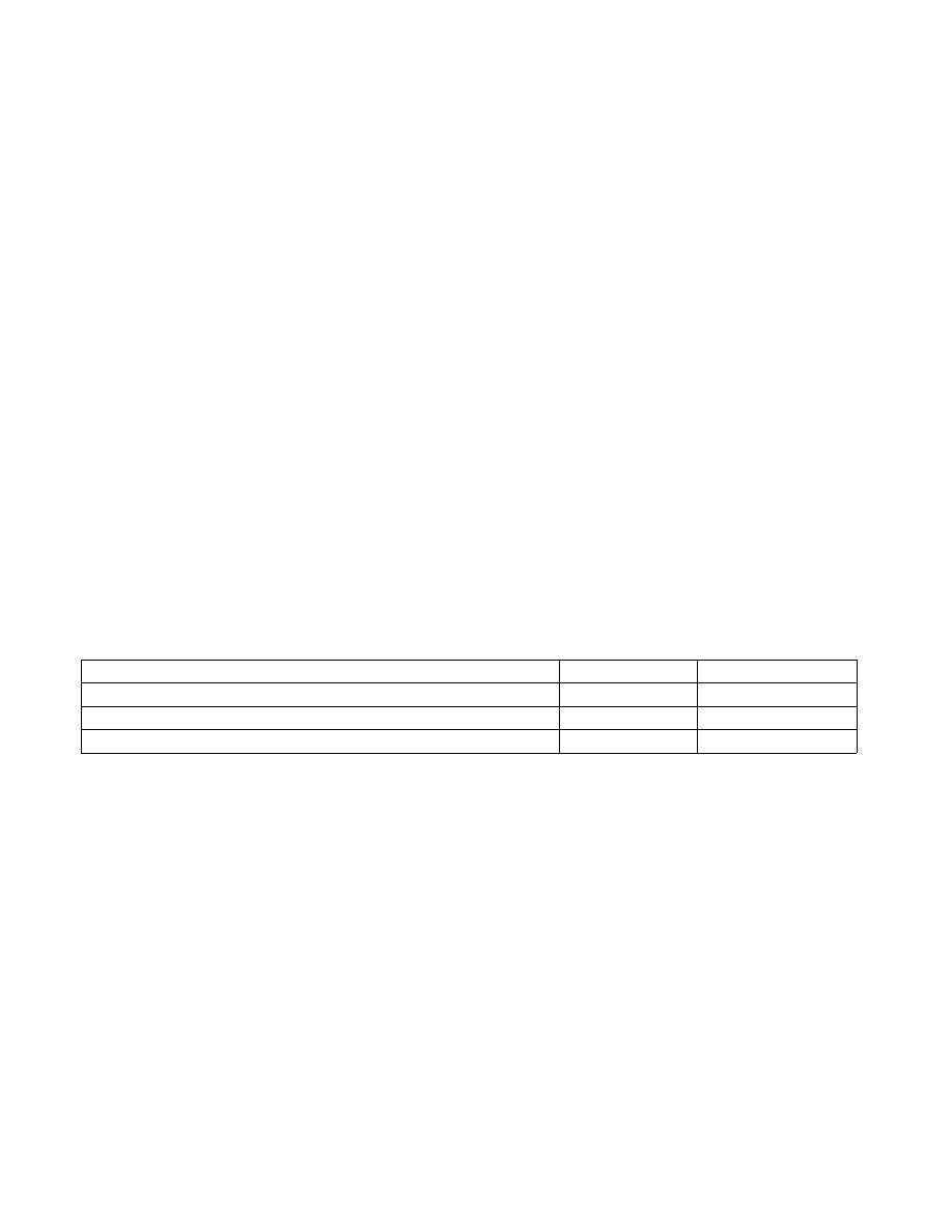
Table 17-18. LBR MSR Stack Size and TOS Pointer Range for the Pentium
®
4 and the Intel
®
Xeon
®
Processor Family
The registers in the LBR MSR stack and the MSR_LASTBRANCH_TOS MSR are read-only and can be read using the
RDMSR instruction.
Figure 17-13 shows the layout of a branch record in an LBR MSR (or MSR pair). Each branch record consists of two
linear addresses, which represent the “from” and “to” instruction pointers for a branch, interrupt, or exception. The
contents of the from and to addresses differ, depending on the source of the branch:
•
Taken branch — If the record is for a taken branch, the “from” address is the address of the branch instruction
and the “to” address is the target instruction of the branch.
•
Interrupt — If the record is for an interrupt, the “from” address the return instruction pointer (RIP) saved for
the interrupt and the “to” address is the address of the first instruction in the interrupt handler routine. The RIP
is the linear address of the next instruction to be executed upon returning from the interrupt handler.
•
Exception — If the record is for an exception, the “from” address is the linear address of the instruction that
caused the exception to be generated and the “to” address is the address of the first instruction in the exception
handler routine.
DisplayFamily_DisplayModel
Size of LBR Stack
Range of TOS Pointer
Family 0FH, Models 0H-02H; MSRs at locations 1DBH-1DEH.
4
0 to 3
Family 0FH, Models; MSRs at locations 680H-68FH.
16
0 to 15
Family 0FH, Model 03H; MSRs at locations 6C0H-6CFH.
16
0 to 15