10-48 Vol. 3A
ADVANCED PROGRAMMABLE INTERRUPT CONTROLLER (APIC)
If the physical delivery mode is being used, then cycles 15 and 16 represent the APIC ID and cycles 13 and 14 are
considered don't care by the receiver. If the logical delivery mode is being used, then cycles 13 through 16 are the
8-bit logical destination field.
For shorthands of “all-incl-self” and “all-excl-self,” the physical delivery mode and an arbitration priority of 15
(D0:D3 = 1111) are used. The agent sending the message is the only one required to distinguish between the two
cases. It does so using internal information.
When using lowest priority delivery with an existing focus processor, the focus processor identifies itself by driving
10 during cycle 19 and accepts the interrupt. This is an indication to other APICs to terminate arbitration. If the
focus processor has not been found, the short message is extended on-the-fly to the non-focused lowest-priority
message. Note that except for the EOI message, messages generating a checksum or an acceptance error (see
Section 10.5.3, “Error Handling”) terminate after cycle 21.
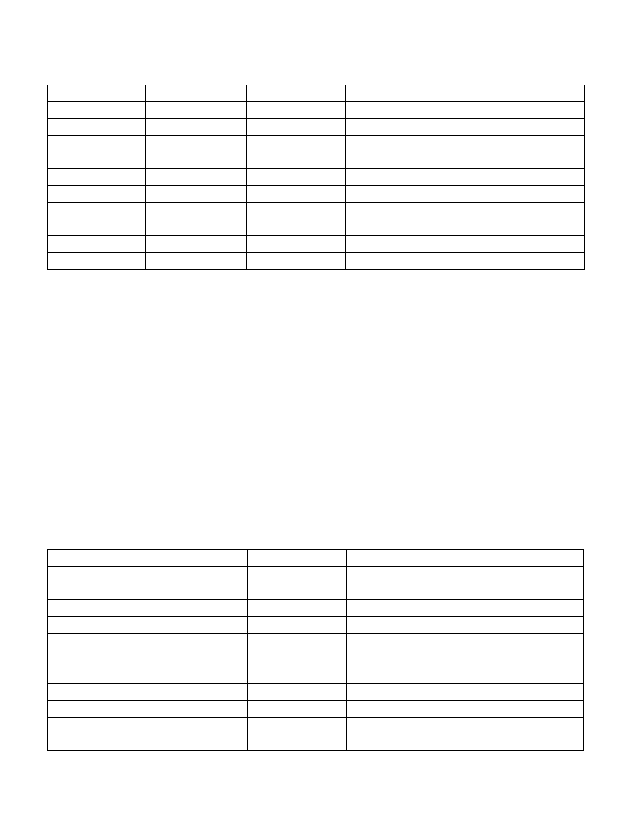
10.13.2.2 Non-focused Lowest Priority Message
These 34-cycle messages (see Table 10-3) are used in the lowest priority delivery mode when a focus processor is
not present. Cycles 1 through 20 are same as for the short message. If during the status cycle (cycle 19) the state
of the (A:A) flags is 10B, a focus processor has been identified, and the short message format is used (see Table
10-2). If the (A:A) flags are set to 00B, lowest priority arbitration is started and the 34-cycles of the non-focused
lowest priority message are competed. For other combinations of status flags, refer to Section 10.13.2.3, “APIC
Bus Status Cycles.”
12
V1
V0
13
D7
D6
D7-D0 = Destination
14
D5
D4
15
D3
D2
16
D1
D0
17
C
C
Checksum for cycles 6-16
18
0
0
19
A
A
Status cycle 0
20
A1
A1
Status cycle 1
21
0
0
Idle
Table 10-3. Non-Focused Lowest Priority Message (34 Cycles)
Cycle
Bit0
Bit1
1
0
1
0 1 = normal
2
ArbID3
0
Arbitration ID bits 3 through 0
3
ArbID2
0
4
ArbID1
0
5
ArbID0
0
6
DM
M2
DM = Destination mode
7
M1
M0
M2-M0 = Delivery mode
8
L
TM
L = Level, TM = Trigger Mode
9
V7
V6
V7-V0 = Interrupt Vector
10
V5
V4
11
V3
V2
Table 10-2. Short Message (21 Cycles) (Contd.)
Cycle
Bit1
Bit0