Vol. 3B 18-119
PERFORMANCE MONITORING
Each counter has an associated external pin (PM0/BP0 and PM1/BP1), which can be used to indicate the state of
the counter to external hardware.
NOTES
The CESR, CTR0, and CTR1 MSRs and the events listed in Table 19-38 are model-specific for the
Pentium processor.
The performance-monitoring events listed in Chapter 19 are intended to be used as guides for
performance tuning. Counter values reported are not guaranteed to be accurate and should be
used as a relative guide for tuning. Known discrepancies are documented where applicable.
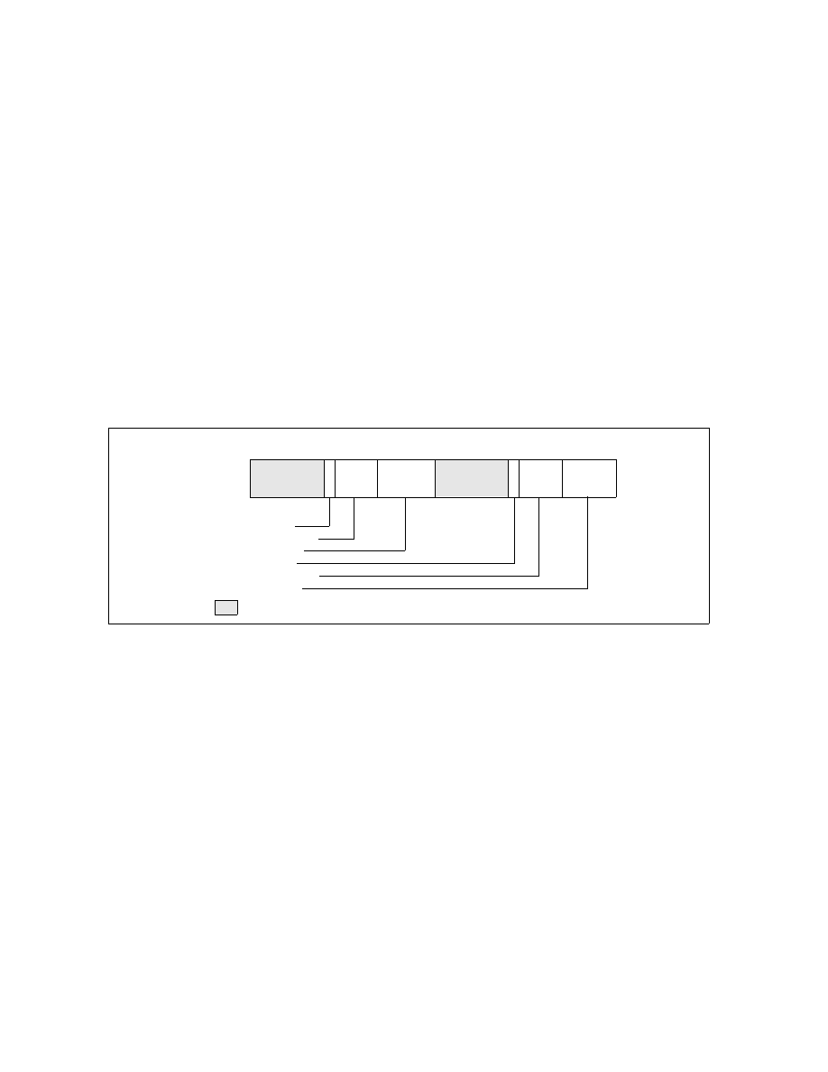
18.23.1 Control and Event Select Register (CESR)
The 32-bit control and event select MSR (CESR) controls the operation of performance-monitoring counters CTR0
and CTR1 and the associated pins (see Figure 18-61). To control each counter, the CESR register contains a 6-bit
event select field (ES0 and ES1), a pin control flag (PC0 and PC1), and a 3-bit counter control field (CC0 and CC1).
The functions of these fields are as follows:
•
ES0 and ES1 (event select) fields (bits 0-5, bits 16-21) — Selects (by entering an event code in the field)
up to two events to be monitored. See Table 19-38 for a list of available event codes.
•
CC0 and CC1 (counter control) fields (bits 6-8, bits 22-24) — Controls the operation of the counter.
Control codes are as follows:
000 — Count nothing (counter disabled)
001 — Count the selected event while CPL is 0, 1, or 2
010 — Count the selected event while CPL is 3
011 — Count the selected event regardless of CPL
100 — Count nothing (counter disabled)
101 — Count clocks (duration) while CPL is 0, 1, or 2
110 — Count clocks (duration) while CPL is 3
111 — Count clocks (duration) regardless of CPL
The highest order bit selects between counting events and counting clocks (duration); the middle bit enables
counting when the CPL is 3; and the low-order bit enables counting when the CPL is 0, 1, or 2.
•
PC0 and PC1 (pin control) flags (bits 9, 25) — Selects the function of the external performance-monitoring
counter pin (PM0/BP0 and PM1/BP1). Setting one of these flags to 1 causes the processor to assert its
associated pin when the counter has overflowed; setting the flag to 0 causes the pin to be asserted when the
counter has been incremented. These flags permit the pins to be individually programmed to indicate the
Figure 18-61. CESR MSR (Pentium Processor Only)
31
PC1—Pin control 1
CC1—Counter control 1
ES1—Event select 1
PC0—Pin control 0
8
0
CC0—Counter control 0
ES0—Event select 0
16 15
21
22
24
Reserved
9
5
6
ESO
CC0
P
C
0
ES1
CC1
P
C
1
25
26
10