Vol. 3B 18-7
PERFORMANCE MONITORING
•
Enable field (lowest 2 bits within each 4-bit control) — When bit 0 is set, performance counting is
enabled in the corresponding fixed-function performance counter to increment while the target condition
associated with the architecture performance event occurred at ring 0. When bit 1 is set, performance counting
is enabled in the corresponding fixed-function performance counter to increment while the target condition
associated with the architecture performance event occurred at ring greater than 0. Writing 0 to both bits stops
the performance counter. Writing a value of 11B enables the counter to increment irrespective of privilege
levels.
•
PMI field (the fourth bit within each 4-bit control) — When set, the logical processor generates an
exception through its local APIC on overflow condition of the respective fixed-function counter.
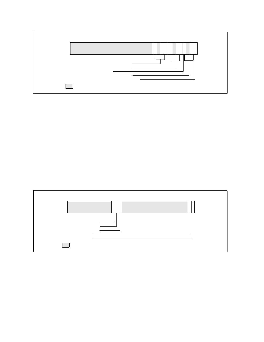
IA32_PERF_GLOBAL_CTRL MSR provides single-bit controls to enable counting of each performance counter.
Figure 18-3 shows the layout of IA32_PERF_GLOBAL_CTRL. Each enable bit in IA32_PERF_GLOBAL_CTRL is
AND’ed with the enable bits for all privilege levels in the respective IA32_PERFEVTSELx or
IA32_PERF_FIXED_CTR_CTRL MSRs to start/stop the counting of respective counters. Counting is enabled if the
AND’ed results is true; counting is disabled when the result is false.
The fixed-function performance counters supported by architectural performance version 2 is listed in Table 18-8,
the pairing between each fixed-function performance counter to an architectural performance event is also shown.
IA32_PERF_GLOBAL_STATUS MSR provides single-bit status for software to query the overflow condition of each
performance counter. IA32_PERF_GLOBAL_STATUS[bit 62] indicates overflow conditions of the DS area data
buffer. IA32_PERF_GLOBAL_STATUS[bit 63] provides a CondChgd bit to indicate changes to the state of perfor-
mance monitoring hardware. Figure 18-4 shows the layout of IA32_PERF_GLOBAL_STATUS. A value of 1 in bits 0,
1, 32 through 34 indicates a counter overflow condition has occurred in the associated counter.
Figure 18-2. Layout of IA32_FIXED_CTR_CTRL MSR
Figure 18-3. Layout of IA32_PERF_GLOBAL_CTRL MSR
Cntr2 — Controls for IA32_FIXED_CTR2
Cntr1 — Controls for IA32_FIXED_CTR1
PMI — Enable PMI on overflow
Cntr0 — Controls for IA32_FIXED_CTR0
8 7
0
ENABLE — 0: disable; 1: OS; 2: User; 3: All ring levels
E
N
P
M
I
11
3
12
1
Reserved
63
2
E
N
E
N
4
9
5
P
P
M
M
I
I
IA32_FIXED_CTR2 enable
IA32_FIXED_CTR1 enable
IA32_FIXED_CTR0 enable
IA32_PMC1 enable
2 1 0
IA32_PMC0 enable
31
32
33
34
35
Reserved
63