Vol. 3B 17-23
DEBUG, BRANCH PROFILE, TSC, AND RESOURCE MONITORING FEATURES
5. Write an interrupt service routine to handle the interrupt. See Section 17.4.9.5, “Writing the DS Interrupt
The following restrictions should be applied to the DS save area.
•
The three DS save area sections should be allocated from a non-paged pool, and marked accessed and dirty. It
is the responsibility of the operating system to keep the pages that contain the buffer present and to mark
them accessed and dirty. The implication is that the operating system cannot do “lazy” page-table entry
propagation for these pages.
•
The DS save area can be larger than a page, but the pages must be mapped to contiguous linear addresses.
The buffer may share a page, so it need not be aligned on a 4-KByte boundary. For performance reasons, the
base of the buffer must be aligned on a doubleword boundary and should be aligned on a cache line boundary.
•
It is recommended that the buffer size for the BTS buffer and the PEBS buffer be an integer multiple of the
corresponding record sizes.
•
The precise event records buffer should be large enough to hold the number of precise event records that can
occur while waiting for the interrupt to be serviced.
•
The DS save area should be in kernel space. It must not be on the same page as code, to avoid triggering self-
modifying code actions.
•
There are no memory type restrictions on the buffers, although it is recommended that the buffers be
designated as WB memory type for performance considerations.
•
Either the system must be prevented from entering A20M mode while DS save area is active, or bit 20 of all
addresses within buffer bounds must be 0.
•
Pages that contain buffers must be mapped to the same physical addresses for all processes, such that any
change to control register CR3 will not change the DS addresses.
•
The DS save area is expected to used only on systems with an enabled APIC. The LVT Performance Counter
entry in the APCI must be initialized to use an interrupt gate instead of the trap gate.
17.4.9.3 Setting Up the BTS Buffer
Three flags in the MSR_DEBUGCTLA MSR (see Table 17-5), IA32_DEBUGCTL (see Figure 17-3), or
MSR_DEBUGCTLB (see Figure 17-16) control the generation of branch records and storing of them in the BTS
buffer; these are TR, BTS, and BTINT. The TR flag enables the generation of BTMs. The BTS flag determines
whether the BTMs are sent out on the system bus (clear) or stored in the BTS buffer (set). BTMs cannot be simul-
taneously sent to the system bus and logged in the BTS buffer. The BTINT flag enables the generation of an inter-
rupt when the BTS buffer is full. When this flag is clear, the BTS buffer is a circular buffer.
The following procedure describes how to set up a DS Save area to collect branch records in the BTS buffer:
1. Place values in the BTS buffer base, BTS index, BTS absolute maximum, and BTS interrupt threshold fields of
the DS buffer management area to set up the BTS buffer in memory.
2. Set the TR and BTS flags in the IA32_DEBUGCTL for Intel Core Solo and Intel Core Duo processors or later
processors (or MSR_DEBUGCTLA MSR for processors based on Intel NetBurst Microarchitecture; or
MSR_DEBUGCTLB for Pentium M processors).
3. Clear the BTINT flag in the corresponding IA32_DEBUGCTL (or MSR_DEBUGCTLA MSR; or MSR_DEBUGCTLB)
if a circular BTS buffer is desired.
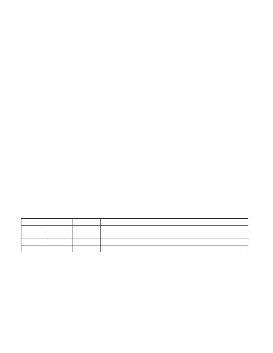
Table 17-5. IA32_DEBUGCTL Flag Encodings
TR
BTS
BTINT
Description
0
X
X
Branch trace messages (BTMs) off
1
0
X
Generate BTMs
1
1
0
Store BTMs in the BTS buffer, used here as a circular buffer
1
1
1
Store BTMs in the BTS buffer, and generate an interrupt when the buffer is nearly full