36-22 Vol. 3C
INTEL® PROCESSOR TRACE
36.2.7.8 IA32_RTIT_OUTPUT_MASK_PTRS MSR
This MSR holds any mask or pointer values needed to indicate where the next byte of trace output should be
written. The meaning of the values held in this MSR depend on whether the ToPA output mechanism is in use. See
Section 36.2.6.2 for details.
The processor updates this MSR while when packet generation is enabled, and those updates are asynchronous to
instruction execution. Therefore, the values in this MSR should be considered unreliable unless packet generation
is disabled (IA32_RTIT_CTL.TraceEn = 0).
Accesses to this MSR are supported only if Intel PT output to memory is supported, hence when either
CPUID.(EAX=14H, ECX=0):ECX[bit 0] or CPUID.(EAX=14H, ECX=0):ECX[bit 2] are set. Otherwise WRMSR or
RDMSR cause a general-protection fault (#GP). If supported, this MSR can be written only when
IA32_RTIT_CTL.TraceEn is 0; otherwise WRMSR causes a general-protection fault (#GP).
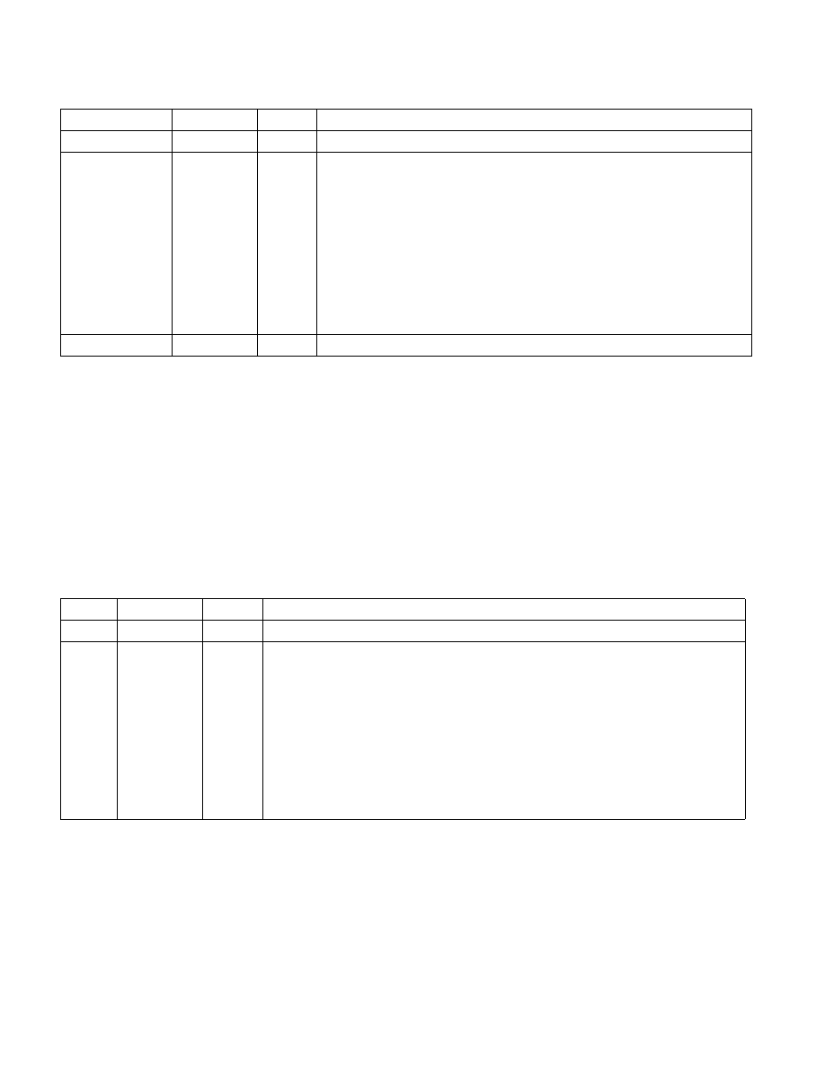
Table 36-8. IA32_RTIT_OUTPUT_BASE MSR
Position
Bit Name
At Reset
Bit Description
6:0
Reserved
0
Must be 0.
MAXPHYADDR-1:7 BasePhysAddr 0
The base physical address. How this address is used depends on the value of
IA32_RTIT_CTL.ToPA:
0: This is the base physical address of a single, contiguous physical output region.
This could be mapped to DRAM or to MMIO, depending on the value.
The base address should be aligned with the size of the region, such that none of
the 1s in the mask value(Section 36.2.7.8) overlap with 1s in the base address. If
the base is not aligned, an operational error will result (see Section 36.3.9).
1: The base physical address of the current ToPA table. The address must be 4K
aligned. Writing an address in which bits 11:7 are non-zero will not cause a #GP, but
an operational error will be signaled once TraceEn is set. See “ToPA Errors” in
Section 36.2.6.2 as well as Section 36.3.9.
63:MAXPHYADDR Reserved
0
Must be 0.
Table 36-9. IA32_RTIT_OUTPUT_MASK_PTRS MSR
Position
Bit Name
At Reset
Bit Description
6:0
LowerMask
7FH
Forced to 1, writes are ignored.
31:7
MaskOrTableO
ffset
0
The use of this field depends on the value of IA32_RTIT_CTL.ToPA:
0: This field holds bits 31:7 of the mask value for the single, contiguous physical output
region. The size of this field indicates that regions can be of size 128B up to 4GB. This value
(combined with the lower 7 bits, which are reserved to 1) will be ANDed with the
OutputOffset field to determine the next write address. All 1s in this field should be
consecutive and starting at bit 7, otherwise the region will not be contiguous, and an
operational error (Section 36.3.9) will be signaled when TraceEn is set.
1: This field holds bits 27:3 of the offset pointer into the current ToPA table. This value can
be added to the IA32_RTIT_OUTPUT_BASE value to produce a pointer to the current ToPA
table entry, which itself is a pointer to the current output region. In this scenario, the lower 7
reserved bits are ignored. This field supports tables up to 256 MBytes in size.