Vol. 3C 34-25
SYSTEM MANAGEMENT MODE
•
Bits 11:3 are reserved.
•
Bits 31:12 contain a value that, when shifted left 12 bits, is the physical address of MSEG (the MSEG base
address).
•
Bits 63:32 are reserved.
The following items detail use of this MSR:
•
The IA32_SMM_MONITOR_CTL MSR is supported only on processors that support the dual-monitor treatment.
1
On other processors, accesses to the MSR using RDMSR or WRMSR generate a general-protection fault
(#GP(0)).
•
A write to the IA32_SMM_MONITOR_CTL MSR using WRMSR generates a general-protection fault (#GP(0)) if
executed outside of SMM or if an attempt is made to set any reserved bit. An attempt to write to the
IA32_SMM_MONITOR_CTL MSR fails if made as part of a VM exit that does not end in SMM or part of a
VM entry that does not begin in SMM.
•
Reads from the IA32_SMM_MONITOR_CTL MSR using RDMSR are allowed any time RDMSR is allowed. The
MSR may be read as part of any VM exit.
•
The dual-monitor treatment can be activated only if the valid bit in the MSR is set to 1.
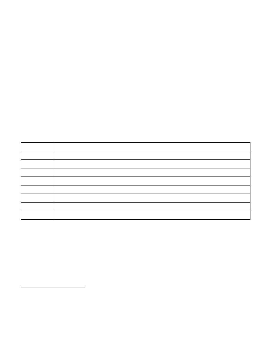
The 32 bytes located at the MSEG base address are called the MSEG header. The format of the MSEG header is
given in Table 34-10 (each field is 32 bits).
To ensure proper behavior in VMX operation, software should maintain the MSEG header in writeback cacheable
memory. Future implementations may allow or require a different memory type.
2
Software should consult the VMX
capability MSR IA32_VMX_BASIC (see Appendix A.1).
SMM code should enable the dual-monitor treatment (by setting the valid bit in IA32_SMM_MONITOR_CTL MSR)
only after establishing the content of the MSEG header as follows:
•
Bytes 3:0 contain the MSEG revision identifier. Different processors may use different MSEG revision identi-
fiers. These identifiers enable software to avoid using an MSEG header formatted for one processor on a
processor that uses a different format. Software can discover the MSEG revision identifier that a processor uses
by reading the VMX capability MSR IA32_VMX_MISC (see Appendix A.6).
1. Software should consult the VMX capability MSR IA32_VMX_BASIC (see Appendix A.1) to determine whether the dual-monitor
treatment is supported.
Table 34-10. Format of MSEG Header
Byte Offset
Field
0
MSEG-header revision identifier
4
SMM-transfer monitor features
8
GDTR limit
12
GDTR base offset
16
CS selector
20
EIP offset
24
ESP offset
28
CR3 offset
2. Alternatively, software may map the MSEG header with the UC memory type; this may be necessary, depending on how memory is
organized. Doing so is strongly discouraged unless necessary as it will cause the performance of transitions using those structures
to suffer significantly. In addition, the processor will continue to use the memory type reported in the VMX capability MSR
IA32_VMX_BASIC with exceptions noted in Appendix A.1.