Vol. 1 9-3
PROGRAMMING WITH INTEL® MMX™ TECHNOLOGY
Although MMX registers are defined in the IA-32 architecture as separate registers, they are aliased to the registers
in the FPU data register stack (R0 through R7).
See also Section 9.5, “Compatibility with x87 FPU Architecture.”
9.2.3 MMX
Data
Types
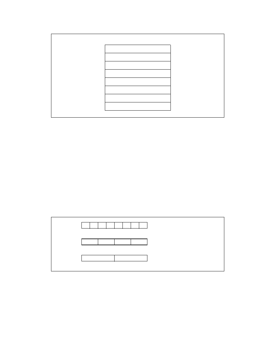
MMX technology introduced the following 64-bit data types to the IA-32 architecture (see Figure 9-3):
•
64-bit packed byte integers — eight packed bytes
•
64-bit packed word integers — four packed words
•
64-bit packed doubleword integers — two packed doublewords
MMX instructions move 64-bit packed data types (packed bytes, packed words, or packed doublewords) and the
quadword data type between MMX registers and memory or between MMX registers in 64-bit blocks. However,
when performing arithmetic or logical operations on the packed data types, MMX instructions operate in parallel on
the individual bytes, words, or doublewords contained in MMX registers (see Section 9.2.5, “Single Instruction,
Multiple Data (SIMD) Execution Model”).
9.2.4
Memory Data Formats
When stored in memory: bytes, words and doublewords in the packed data types are stored in consecutive
addresses. The least significant byte, word, or doubleword is stored at the lowest address and the most significant
byte, word, or doubleword is stored at the high address. The ordering of bytes, words, or doublewords in memory
is always little endian. That is, the bytes with the low addresses are less significant than the bytes with high
addresses.
Figure 9-2. MMX Register Set
Figure 9-3. Data Types Introduced with the MMX Technology
MM7
MM6
MM5
MM4
MM3
MM2
MM1
MM0
63
0
Packed Word Integers
Packed Byte Integers
Packed Doubleword Integers
0
63
0
63
0
63