2-14 Vol. 3A
SYSTEM ARCHITECTURE OVERVIEW
•
CR8 — Provides read and write access to the Task Priority Register (TPR). It specifies the priority threshold
value that operating systems use to control the priority class of external interrupts allowed to interrupt the
processor. This register is available only in 64-bit mode. However, interrupt filtering continues to apply in
compatibility mode.
When loading a control register, reserved bits should always be set to the values previously read. The flags in
control registers are:
PG
Paging (bit 31 of CR0) — Enables paging when set; disables paging when clear. When paging is
disabled, all linear addresses are treated as physical addresses. The PG flag has no effect if the PE flag (bit
0 of register CR0) is not also set; setting the PG flag when the PE flag is clear causes a general-protection
exception (#GP). See also: Chapter 4, “Paging.”
On Intel 64 processors, enabling and disabling IA-32e mode operation also requires modifying CR0.PG.
CD
Cache Disable (bit 30 of CR0) — When the CD and NW flags are clear, caching of memory locations for
the whole of physical memory in the processor’s internal (and external) caches is enabled. When the CD
flag is set, caching is restricted as described in Table 11-5. To prevent the processor from accessing and
updating its caches, the CD flag must be set and the caches must be invalidated so that no cache hits can
occur.
See also: Section 11.5.3, “Preventing Caching,” and Section 11.5, “Cache Control.”
NW
Not Write-through (bit 29 of CR0) — When the NW and CD flags are clear, write-back (for Pentium 4,
Intel Xeon, P6 family, and Pentium processors) or write-through (for Intel486 processors) is enabled for
writes that hit the cache and invalidation cycles are enabled. See Table 11-5 for detailed information about
the effect of the NW flag on caching for other settings of the CD and NW flags.
AM
Alignment Mask (bit 18 of CR0) — Enables automatic alignment checking when set; disables alignment
checking when clear. Alignment checking is performed only when the AM flag is set, the AC flag in the
EFLAGS register is set, CPL is 3, and the processor is operating in either protected or virtual-8086 mode.
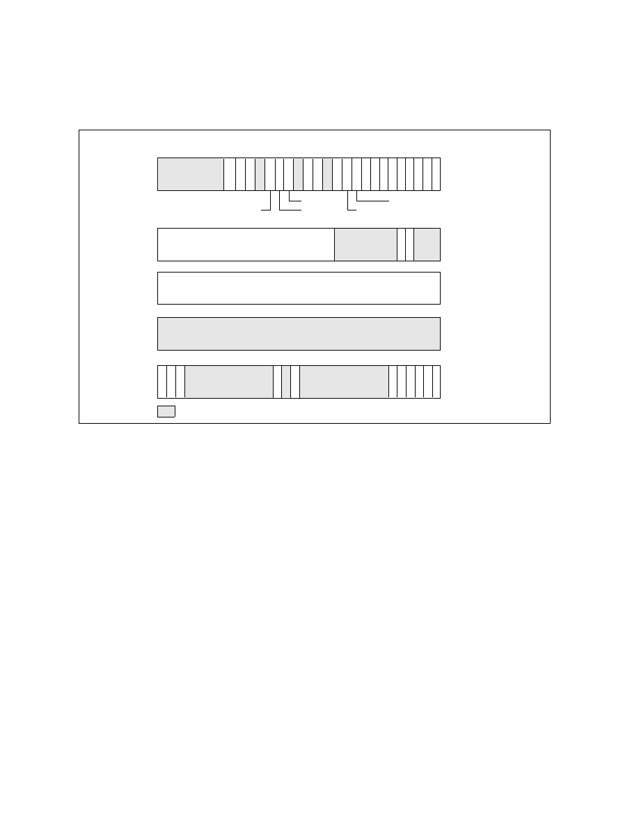
Figure 2-7. Control Registers
CR1
W
P
A
M
Page-Directory Base
V
M
E
P
S
E
T
S
D
D
E
P
V
I
P
G
E
M
C
E
P
A
E
P
C
E
N
W
P
G
C
D
P
W
T
P
C
D
Page-Fault Linear Address
P
E
E
M
M
P
T
S
N
E
E
T
CR2
CR0
CR4
Reserved
CR3
Reserved
31
29
30
28
19 18 17 16 15
6 5 4 3 2 1 0
31(63)
0
31(63)
0
31(63)
12 11
5 4 3 2
31(63)
9 8 7 6 5 4 3 2 1 0
(PDBR)
13 12 11 10
OSFXSR
OSXMMEXCPT
V
M
X
E
E
X
M
S
14
18
OSXSAVE
PCIDE
17
S
M
E
P
20
FSGSBASE
16 15
S
M
A
P
22 21
P
K
E
U
M
I
P