18-56 Vol. 3B
PERFORMANCE MONITORING
programmed latency threshold specified separately in a MSR. Stores are ignored when this event is
programmed. The CMASK or INV fields of the IA32_PerfEvtSelX register used for counting load latency must be
0. Writing other values will result in undefined behavior.
•
The MSR_PEBS_LD_LAT_THRESHOLD MSR is programmed with the desired latency threshold in core clock
cycles. Loads with latencies greater than this value are eligible for counting and latency data reporting. The
minimum value that may be programmed in this register is 3 (the minimum detectable load latency is 4 core
clock cycles).
•
The PEBS enable bit in the IA32_PEBS_ENABLE register is set for the corresponding IA32_PMCx counter
register. This means that both the PEBS_EN_CTRX and LL_EN_CTRX bits must be set for the counter(s) of
interest. For example, to enable load latency on counter IA32_PMC0, the IA32_PEBS_ENABLE register must be
programmed with the 64-bit value 00000001.00000001H.
•
When Load latency event is enabled, no other PEBS event can be configured with other counters.
When the load-latency facility is enabled, load operations are randomly selected by hardware and tagged to carry
information related to data source locality and latency. Latency and data source information of tagged loads are
updated internally. The MEM_TRANS_RETIRED event for load latency counts only tagged retired loads. If a load is
cancelled it will not be counted and the internal state of the load latency facility will not be updated. In this case the
hardware will tag the next available load.
When a PEBS assist occurs, the last update of latency and data source information are captured by the assist and
written as part of the PEBS record. The PEBS sample after value (SAV), specified in PEBS CounterX Reset, operates
orthogonally to the tagging mechanism. Loads are randomly tagged to collect latency data. The SAV controls the
number of tagged loads with latency information that will be written into the PEBS record field by the PEBS assists.
The load latency data written to the PEBS record will be for the last tagged load operation which retired just before
the PEBS assist was invoked.
The physical layout of the PEBS records is the same as shown in Table 18-23. The specificity of Data Source entry
at offset A0H has been enhanced to report three piece of information.
The layout of MSR_PEBS_LD_LAT_THRESHOLD is the same as shown in Figure 18-23.
18.9.4.3 Precise Store Facility
Processors based on Intel microarchitecture code name Sandy Bridge offer a precise store capability that comple-
ments the load latency facility. It provides a means to profile store memory references in the system.
Precise stores leverage the PEBS facility and provide additional information about sampled stores. Having precise
memory reference events with linear address information for both loads and stores can help programmers improve
data structure layout, eliminate remote node references, and identify cache-line conflicts in NUMA systems.
Only IA32_PMC3 can be used to capture precise store information. After enabling this facility, counter overflows will
initiate the generation of PEBS records as previously described in PEBS. Upon counter overflow hardware captures
the linear address and other status information of the next store that retires. This information is then written to the
PEBS record.
To enable the precise store facility, software must complete the following steps. Please note that the precise store
facility relies on the PEBS facility, so the PEBS configuration requirements must be completed before attempting to
capture precise store information.
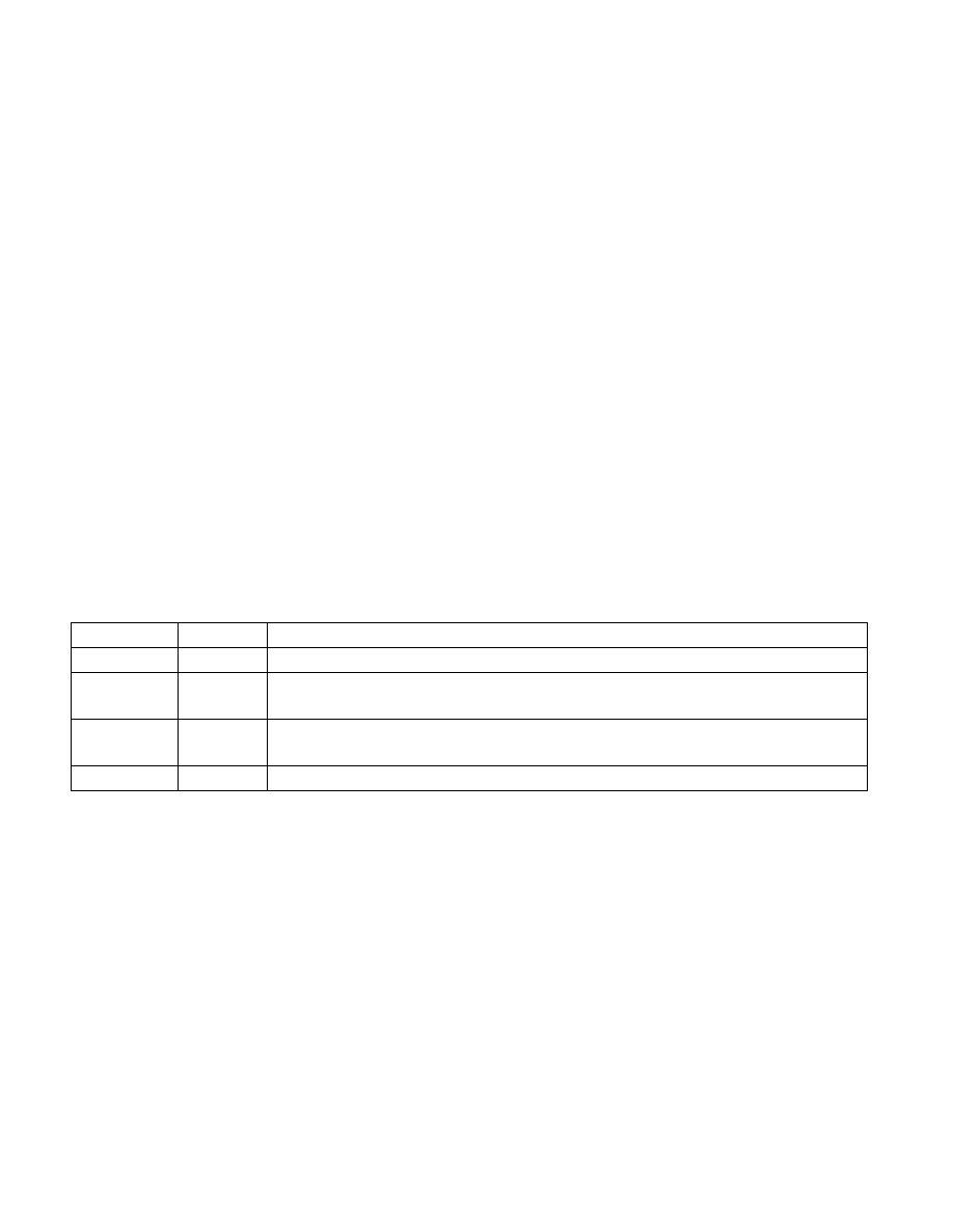
Table 18-33. Layout of Data Source Field of Load Latency Record
Field Position
Description
Source
3:0
See Table 18-24
STLB_MISS
4
0: The load did not miss the STLB (hit the DTLB or STLB).
1: The load missed the STLB.
Lock
5
0: The load was not part of a locked transaction.
1: The load was part of a locked transaction.
Reserved
63:6
Reserved