Vol. 3B 15-21
MACHINE-CHECK ARCHITECTURE
The “Interpretation” column in the table indicates the name of a compound error. The name is constructed by
substituting mnemonics for the sub-field names given within curly braces. For example, the error code
ICACHEL1_RD_ERR is constructed from the form:
{TT}CACHE{LL}_{RRRR}_ERR,
where {TT} is replaced by I, {LL} is replaced by L1, and {RRRR} is replaced by RD.
For more information on the “Form” and “Interpretation” columns, see Sections Section 15.9.2.1, “Correction
Report Filtering (F) Bit” through Section 15.9.2.5, “Bus and Interconnect Errors”.
15.9.2.1 Correction Report Filtering (F) Bit
Starting with Intel Core Duo processors, bit 12 in the “Form” column in Table 15-9 is used to indicate that a partic-
ular posting to a log may be the last posting for corrections in that line/entry, at least for some time:
•
0 in bit 12 indicates “normal” filtering (original P6/Pentium4/Atom/Xeon processor meaning).
•
1 in bit 12 indicates “corrected” filtering (filtering is activated for the line/entry in the posting). Filtering means
that some or all of the subsequent corrections to this entry (in this structure) will not be posted. The enhanced
error reporting introduced with the Intel Core Duo processors is based on tracking the lines affected by
repeated corrections (see Section 15.4, “Enhanced Cache Error reporting”). This capability is indicated by
IA32_MCG_CAP[11]. Only the first few correction events for a line are posted; subsequent redundant
correction events to the same line are not posted. Uncorrected events are always posted.
The behavior of error filtering after crossing the yellow threshold is model-specific. Filtering has meaning only for
corrected errors (UC=0 in IA32_MCi_STATUS MSR). System software must ignore filtering bit (12) for uncorrected
errors.
15.9.2.2 Transaction Type (TT) Sub-Field
The 2-bit TT sub-field (Table 15-10) indicates the type of transaction (data, instruction, or generic). The sub-field
applies to the TLB, cache, and interconnect error conditions. Note that interconnect error conditions are primarily
associated with P6 family and Pentium processors, which utilize an external APIC bus separate from the system
bus. The generic type is reported when the processor cannot determine the transaction type.
15.9.2.3 Level (LL) Sub-Field
The 2-bit LL sub-field (see Table 15-11) indicates the level in the memory hierarchy where the error occurred (level
0, level 1, level 2, or generic). The LL sub-field also applies to the TLB, cache, and interconnect error conditions.
The Pentium 4, Intel Xeon, Intel Atom, and P6 family processors support two levels in the cache hierarchy and one
level in the TLBs. Again, the generic type is reported when the processor cannot determine the hierarchy level.
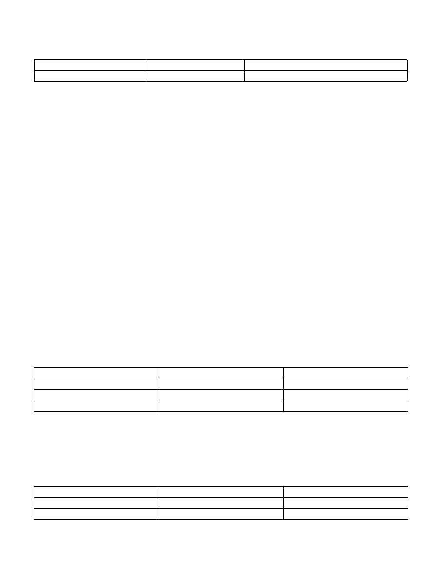
Cache Hierarchy Errors
000F 0001 RRRR TTLL
{TT}CACHE{LL}_{RRRR}_ERR
Bus and Interconnect Errors
000F 1PPT RRRR IILL
BUS{LL}_{PP}_{RRRR}_{II}_{T}_ERR
Table 15-10. Encoding for TT (Transaction Type) Sub-Field
Transaction Type
Mnemonic
Binary Encoding
Instruction
I
00
Data
D
01
Generic
G
10
Table 15-11. Level Encoding for LL (Memory Hierarchy Level) Sub-Field
Hierarchy Level
Mnemonic
Binary Encoding
Level 0
L0
00
Level 1
L1
01
Table 15-9. IA32_MCi_Status [15:0] Compound Error Code Encoding (Contd.)