Vol. 3A 11-25
MEMORY CACHE CONTROL
All other bits in the IA32_MTRR_PHYSBASEn and IA32_MTRR_PHYSMASKn registers are reserved; the processor
generates a general-protection exception (#GP) if software attempts to write to them.
Some mask values can result in ranges that are not continuous. In such ranges, the area not mapped by the mask
value is set to the default memory type, unless some other MTRR specifies a type for that range. Intel does not
encourage the use of “discontinuous” ranges.
NOTE
It is possible for software to parse the memory descriptions that BIOS provides by using the
ACPI/INT15 e820 interface mechanism. This information then can be used to determine how
MTRRs are initialized (for example: allowing the BIOS to define valid memory ranges and the
maximum memory range supported by the platform, including the processor).
See Section 11.11.4.1, “MTRR Precedences,” for information on overlapping variable MTRR ranges.
11.11.2.4 System-Management Range Register Interface
If IA32_MTRRCAP[bit 11] is set, the processor supports the SMRR interface to restrict access to a specified
memory address range used by system-management mode (SMM) software (see Section 34.4.2.1). If the SMRR
interface is supported, SMM software is strongly encouraged to use it to protect the SMI code and data stored by
SMI handler in the SMRAM region.
The system-management range registers consist of a pair of MSRs (see Figure 11-8). The IA32_SMRR_PHYSBASE
MSR defines the base address for the SMRAM memory range and the memory type used to access it in SMM. The
IA32_SMRR_PHYSMASK MSR contains a valid bit and a mask that determines the SMRAM address range protected
by the SMRR interface. These MSRs may be written only in SMM; an attempt to write them outside of SMM causes
a general-protection exception.
1
Figure 11-8 shows flags and fields in these registers. The functions of these flags and fields are the following:
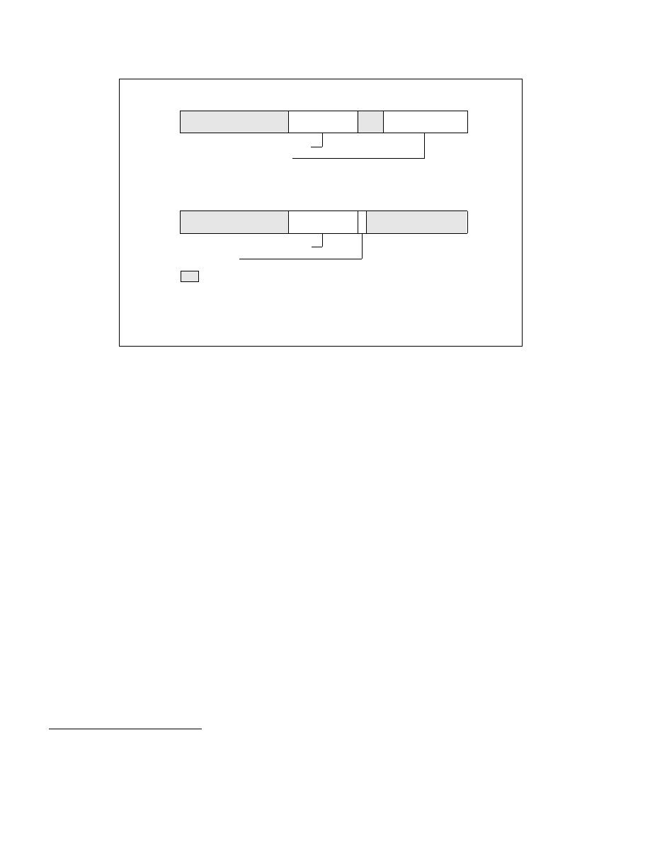
Figure 11-7. IA32_MTRR_PHYSBASEn and IA32_MTRR_PHYSMASKn Variable-Range Register Pair
1. For some processor models, these MSRs can be accessed by RDMSR and WRMSR only if the SMRR interface has been enabled using
a model-specific bit in the IA32_FEATURE_CONTROL MSR.
V — Valid
PhysMask — Sets range mask
IA32_MTRR_PHYSMASKn Register
63
0
Reserved
10
11
12
V
Reserved
MAXPHYADDR
PhysMask
Type — Memory type for range
PhysBase — Base address of range
IA32_MTRR_PHYSBASEn Register
63
0
Reserved
11
12
Type
MAXPHYADDR
PhysBase
7
8
Reserved
MAXPHYADDR: The bit position indicated by MAXPHYADDR depends on the maximum
physical address range supported by the processor. It is reported by CPUID leaf
function 80000008H. If CPUID does not support leaf 80000008H, the processor
supports 36-bit physical address size, then bit PhysMask consists of bits 35:12, and
bits 63:36 are reserved.