Vol. 3A 9-15
PROCESSOR MANAGEMENT AND INITIALIZATION
•
Load the necessary protected-mode system data structures into RAM.
•
Load the system registers with the necessary pointers to the data structures and the appropriate flag settings
for protected-mode operation.
•
Switch the processor to protected mode.
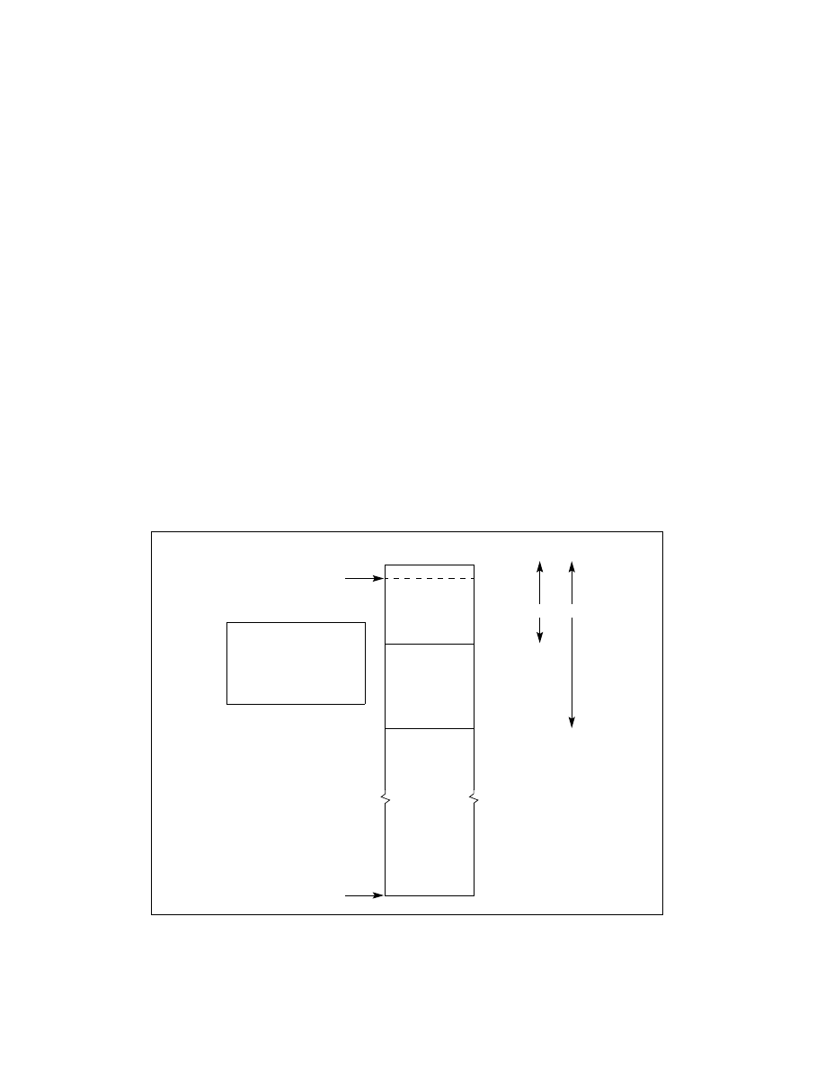
Figure 9-3 shows the physical memory layout for the processor following a hardware reset and the starting point
of this example. The EPROM that contains the initialization code resides at the upper end of the processor’s physical
memory address range, starting at address FFFFFFFFH and going down from there. The address of the first instruc-
tion to be executed is at FFFFFFF0H, the default starting address for the processor following a hardware reset.
The main steps carried out in this example are summarized in Table 9-5. The source listing for the example (with
the filename STARTUP.ASM) is given in Example 9-1. The line numbers given in Table 9-5 refer to the source listing.
The following are some additional notes concerning this example:
•
When the processor is switched into protected mode, the original code segment base-address value of
FFFF0000H (located in the hidden part of the CS register) is retained and execution continues from the current
offset in the EIP register. The processor will thus continue to execute code in the EPROM until a far jump or call
is made to a new code segment, at which time, the base address in the CS register will be changed.
•
Maskable hardware interrupts are disabled after a hardware reset and should remain disabled until the
necessary interrupt handlers have been installed. The NMI interrupt is not disabled following a reset. The NMI#
pin must thus be inhibited from being asserted until an NMI handler has been loaded and made available to the
processor.
•
The use of a temporary GDT allows simple transfer of tables from the EPROM to anywhere in the RAM area. A
GDT entry is constructed with its base pointing to address 0 and a limit of 4 GBytes. When the DS and ES
registers are loaded with this descriptor, the temporary GDT is no longer needed and can be replaced by the
application GDT.
•
This code loads one TSS and no LDTs. If more TSSs exist in the application, they must be loaded into RAM. If
there are LDTs they may be loaded as well.
Figure 9-3. Processor State After Reset
0
FFFF FFFFH
After Reset
[CS.BASE+EIP]
FFFF FFF0H
EIP = 0000 FFF0H
[SP, DS, SS, ES]
FFFF 0000H
64K EPROM
CS.BASE = FFFF 0000H
DS.BASE = 0H
ES.BASE = 0H
SS.BASE = 0H
ESP = 0H