Vol. 3A 3-7
PROTECTED-MODE MEMORY MANAGEMENT
If paging is not used, the processor maps the linear address directly to a physical address (that is, the linear
address goes out on the processor’s address bus). If the linear address space is paged, a second level of address
translation is used to translate the linear address into a physical address.
See also: Chapter 4, “Paging.”
3.4.1
Logical Address Translation in IA-32e Mode
In IA-32e mode, an Intel 64 processor uses the steps described above to translate a logical address to a linear
address. In 64-bit mode, the offset and base address of the segment are 64-bits instead of 32 bits. The linear
address format is also 64 bits wide and is subject to the canonical form requirement.
Each code segment descriptor provides an L bit. This bit allows a code segment to execute 64-bit code or legacy
32-bit code by code segment.
3.4.2 Segment
Selectors
A segment selector is a 16-bit identifier for a segment (see Figure 3-6). It does not point directly to the segment,
but instead points to the segment descriptor that defines the segment. A segment selector contains the following
items:
Index
(Bits 3 through 15) — Selects one of 8192 descriptors in the GDT or LDT. The processor multiplies
the index value by 8 (the number of bytes in a segment descriptor) and adds the result to the base
address of the GDT or LDT (from the GDTR or LDTR register, respectively).
TI (table indicator) flag
(Bit 2) — Specifies the descriptor table to use: clearing this flag selects the GDT; setting this flag
selects the current LDT.
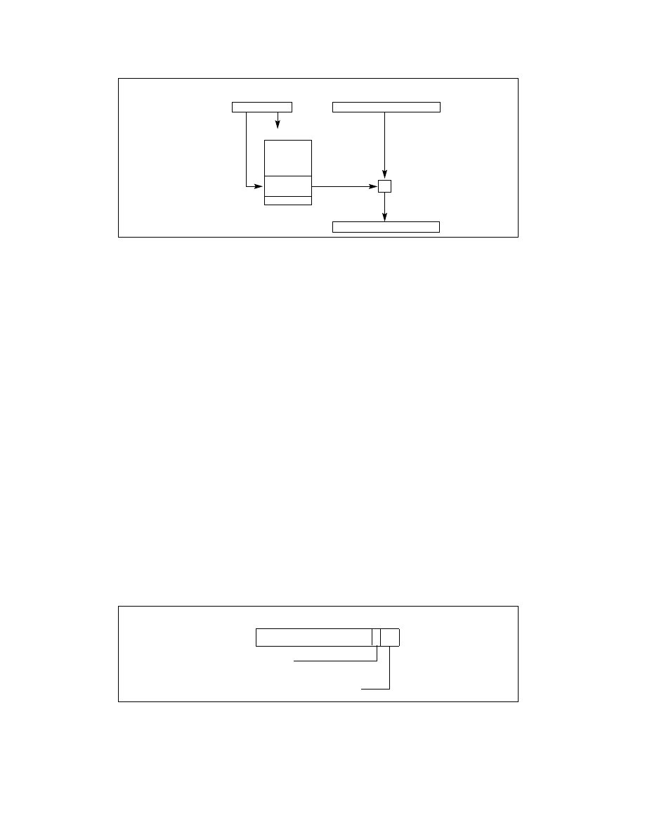
Figure 3-5. Logical Address to Linear Address Translation
Figure 3-6. Segment Selector
Offset (Effective Address)
0
Base Address
Descriptor Table
Segment
Descriptor
31(63)
Seg. Selector
0
15
Logical
Address
+
Linear Address
0
31(63)
15
3 2 1 0
T
I
Index
Table Indicator
0 = GDT
1 = LDT
Requested Privilege Level (RPL)
RPL