18-100 Vol. 3B
PERFORMANCE MONITORING
•
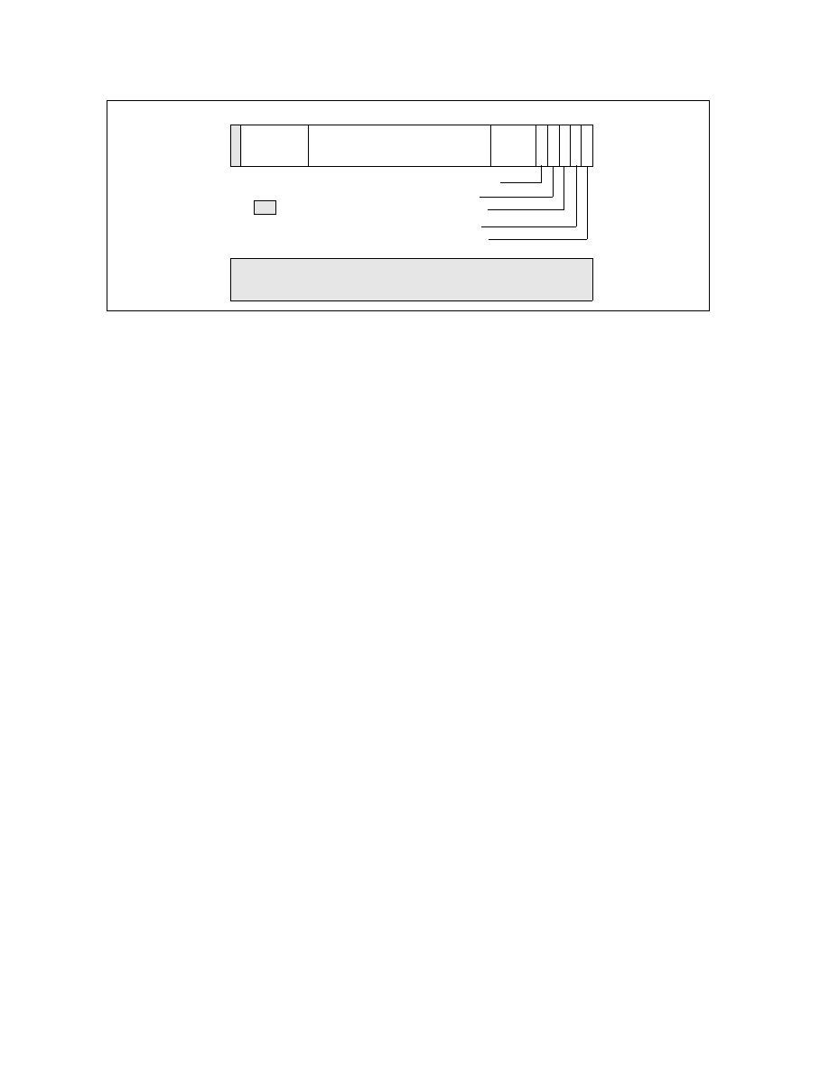
T1_OS flag, bit 1 — When set, events are counted when thread 1 (logical processor 1) is executing at CPL of
0. This privilege level is generally reserved for protected operating system code. (When both the T1_OS and
T1_USR flags are set, thread 1 events are counted at all privilege levels.)
•
T0_USR flag, bit 2 — When set, events are counted when thread 0 (logical processor 0) is executing at a CPL
of 1, 2, or 3.
•
T0_OS flag, bit 3 — When set, events are counted when thread 0 (logical processor 0) is executing at CPL of
0. (When both the T0_OS and T0_USR flags are set, thread 0 events are counted at all privilege levels.)
•
Tag enable, bit 4 — When set, enables tagging of μops to assist in at-retirement event counting; when clear,
disables tagging. See Section 18.15.6, “At-Retirement Counting.”
•
Tag value field, bits 5 through 8 — Selects a tag value to associate with a μop to assist in at-retirement
event counting.
•
Event mask field, bits 9 through 24 — Selects events to be counted from the event class selected with the
event select field.
•
Event select field, bits 25 through 30) — Selects a class of events to be counted. The events within this
class that are counted are selected with the event mask field.
The T0_OS and T0_USR flags and the T1_OS and T1_USR flags allow event counting and sampling to be specified
for a specific logical processor (0 or 1) within an Intel Xeon processor MP (See also: Section 8.4.5, “Identifying
Logical Processors in an MP System,” in the Intel® 64 and IA-32 Architectures Software Developer’s Manual,
Volume 3A).
Not all performance monitoring events can be detected within an Intel Xeon processor MP on a per logical processor
basis (see Section 18.16.4, “Performance Monitoring Events”). Some sub-events (specified by an event mask bits)
are counted or sampled without regard to which logical processor is associated with the detected event.
18.16.2 CCCR
MSRs
Figure 18-48 shows the layout of a CCCR MSR in processors supporting Intel Hyper-Threading Technology. The
functions of the flags and fields are as follows:
•
Enable flag, bit 12 — When set, enables counting; when clear, the counter is disabled. This flag is cleared on
reset
•
ESCR select field, bits 13 through 15 — Identifies the ESCR to be used to select events to be counted with
the counter associated with the CCCR.
•
Active thread field, bits 16 and 17 — Enables counting depending on which logical processors are active
(executing a thread). This field enables filtering of events based on the state (active or inactive) of the logical
processors. The encodings of this field are as follows:
Figure 18-47. Event Selection Control Register (ESCR) for the Pentium 4 Processor, Intel Xeon Processor and Intel
Xeon Processor MP Supporting Hyper-Threading Technology
31
24
8
0
1
2
3
4
9
25
30
63
32
Reserved
Event Mask
Event
Select
T0_USR
T0_OS
5
Tag Enable
Tag
Value
T1_USR
T1_OS
Reserved