Vol. 3B 18-101
PERFORMANCE MONITORING
00 — None. Count only when neither logical processor is active.
01 — Single. Count only when one logical processor is active (either 0 or 1).
10 — Both. Count only when both logical processors are active.
11 — Any. Count when either logical processor is active.
A halted logical processor or a logical processor in the “wait for SIPI” state is considered inactive.
•
Compare flag, bit 18 — When set, enables filtering of the event count; when clear, disables filtering. The
filtering method is selected with the threshold, complement, and edge flags.
•
Complement flag, bit 19 — Selects how the incoming event count is compared with the threshold value.
When set, event counts that are less than or equal to the threshold value result in a single count being
delivered to the performance counter; when clear, counts greater than the threshold value result in a count
being delivered to the performance counter (see Section 18.15.5.2, “Filtering Events”). The compare flag is not
active unless the compare flag is set.
•
Threshold field, bits 20 through 23 — Selects the threshold value to be used for comparisons. The
processor examines this field only when the compare flag is set, and uses the complement flag setting to
determine the type of threshold comparison to be made. The useful range of values that can be entered in this
field depend on the type of event being counted (see Section 18.15.5.2, “Filtering Events”).
•
Edge flag, bit 24 — When set, enables rising edge (false-to-true) edge detection of the threshold comparison
output for filtering event counts; when clear, rising edge detection is disabled. This flag is active only when the
compare flag is set.
•
FORCE_OVF flag, bit 25 — When set, forces a counter overflow on every counter increment; when clear,
overflow only occurs when the counter actually overflows.
•
OVF_PMI_T0 flag, bit 26 — When set, causes a performance monitor interrupt (PMI) to be sent to logical
processor 0 when the counter overflows occurs; when clear, disables PMI generation for logical processor 0.
Note that the PMI is generate on the next event count after the counter has overflowed.
•
OVF_PMI_T1 flag, bit 27 — When set, causes a performance monitor interrupt (PMI) to be sent to logical
processor 1 when the counter overflows occurs; when clear, disables PMI generation for logical processor 1.
Note that the PMI is generate on the next event count after the counter has overflowed.
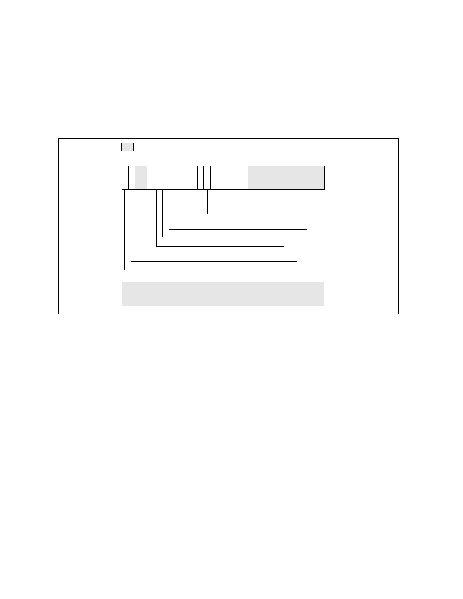
Figure 18-48. Counter Configuration Control Register (CCCR)
63
32
Reserved
Reserved
Active Thread
Compare
Enable
31
24 23
20 19
16 15
12 11
0
17
18
25
26
27
29
30
Edge
FORCE_OVF
OVF_PMI_T0
Threshold
Cascade
OVF
Complement
Reserved
13
ESCR
Select
OVF_PMI_T1
Reserved