18-88 Vol. 3B
PERFORMANCE MONITORING
•
FORCE_OVF flag, bit 25 — When set, forces a counter overflow on every counter increment; when clear,
overflow only occurs when the counter actually overflows.
•
OVF_PMI flag, bit 26 — When set, causes a performance monitor interrupt (PMI) to be generated when the
counter overflows occurs; when clear, disables PMI generation. Note that the PMI is generated on the next
event count after the counter has overflowed.
•
Cascade flag, bit 30 — When set, enables counting on one counter of a counter pair when its alternate
counter in the other the counter pair in the same counter group overflows (see Section 18.15.2, “Performance
Counters,” for further details); when clear, disables cascading of counters.
•
OVF flag, bit 31 — Indicates that the counter has overflowed when set. This flag is a sticky flag that must be
explicitly cleared by software.
The CCCRs are initialized to all 0s on reset.
The events that an enabled performance counter actually counts are selected and filtered by the following flags and
fields in the ESCR and CCCR registers and in the qualification order given:
1. The event select and event mask fields in the ESCR select a class of events to be counted and one or more
event types within the class, respectively.
2. The OS and USR flags in the ESCR selected the privilege levels at which events will be counted.
3. The ESCR select field of the CCCR selects the ESCR. Since each counter has several ESCRs associated with it,
one ESCR must be chosen to select the classes of events that may be counted.
4. The compare and complement flags and the threshold field of the CCCR select an optional threshold to be used
in qualifying an event count.
5. The edge flag in the CCCR allows events to be counted only on rising-edge transitions.
The qualification order in the above list implies that the filtered output of one “stage” forms the input for the next.
For instance, events filtered using the privilege level flags can be further qualified by the compare and complement
flags and the threshold field, and an event that matched the threshold criteria, can be further qualified by edge
detection.
The uses of the flags and fields in the CCCRs are discussed in greater detail in Section 18.15.5, “Programming the
Performance Counters for Non-Retirement Events.”
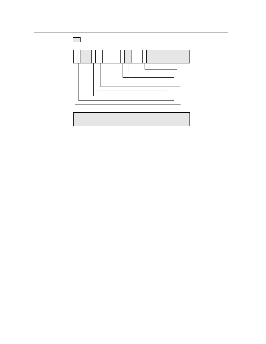
Figure 18-45. Counter Configuration Control Register (CCCR)
63
32
Reserved
Reserved
Reserved: Must be set to 11B
Compare
Enable
31
24 23
20 19
16 15
12 11
0
17
18
25
26
27
29
30
Edge
FORCE_OVF
OVF_PMI
Threshold
Cascade
OVF
Complement
Reserved
13
ESCR
Select
Reserved