Vol. 3B 18-45
PERFORMANCE MONITORING
18.8.2.2 Uncore Performance Event Configuration Facility
MSR_UNCORE_PerfEvtSel0 through MSR_UNCORE_PerfEvtSel7 are used to select performance event and
configure the counting behavior of the respective uncore performance counter. Each uncore PerfEvtSel MSR is
paired with an uncore performance counter. Each uncore counter must be locally configured using the corre-
sponding MSR_UNCORE_PerfEvtSelx and counting must be enabled using the respective EN_PCx bit in
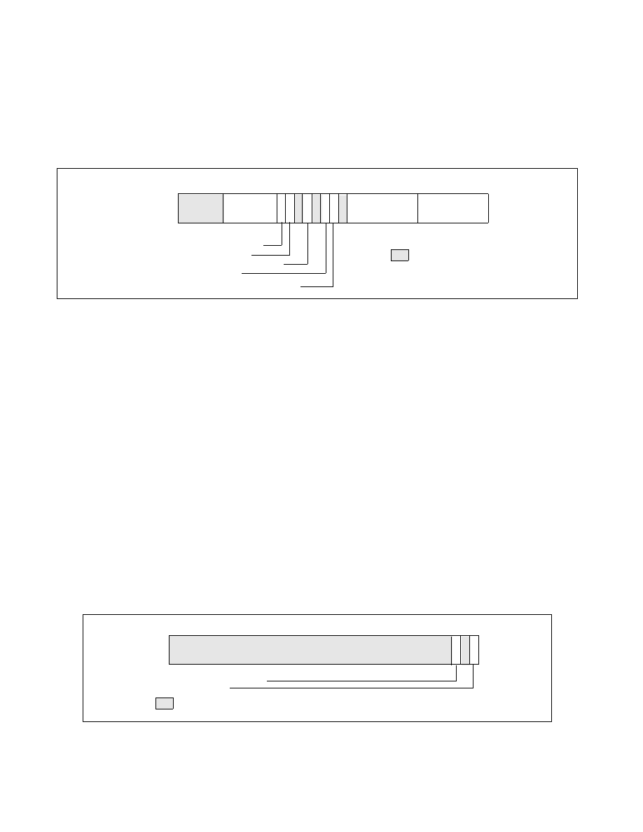
MSR_UNCORE_PERF_GLOBAL_CTRL. Figure 18-28 shows the layout of MSR_UNCORE_PERFEVTSELx.
•
Event Select (bits 7:0): Selects the event logic unit used to detect uncore events.
•
Unit Mask (bits 15:8) : Condition qualifiers for the event selection logic specified in the Event Select field.
•
OCC_CTR_RST (bit17): When set causes the queue occupancy counter associated with this event to be cleared
(zeroed). Writing a zero to this bit will be ignored. It will always read as a zero.
•
Edge Detect (bit 18): When set causes the counter to increment when a deasserted to asserted transition
occurs for the conditions that can be expressed by any of the fields in this register.
•
PMI (bit 20): When set, the uncore will generate an interrupt request when this counter overflowed. This
request will be routed to the logical processors as enabled in the PMI enable bits (EN_PMI_COREx) in the
register MSR_UNCORE_PERF_GLOBAL_CTRL.
•
EN (bit 22): When clear, this counter is locally disabled. When set, this counter is locally enabled and counting
starts when the corresponding EN_PCx bit in MSR_UNCORE_PERF_GLOBAL_CTRL is set.
•
INV (bit 23): When clear, the Counter Mask field is interpreted as greater than or equal to. When set, the
Counter Mask field is interpreted as less than.
•
Counter Mask (bits 31:24): When this field is clear, it has no effect on counting. When set to a value other than
zero, the logical processor compares this field to the event counts on each core clock cycle. If INV is clear and
the event counts are greater than or equal to this field, the counter is incremented by one. If INV is set and the
event counts are less than this field, the counter is incremented by one. Otherwise the counter is not incre-
mented.
Figure 18-29 shows the layout of MSR_UNCORE_FIXED_CTR_CTRL.
Figure 18-28. Layout of MSR_UNCORE_PERFEVTSELx MSRs
Figure 18-29. Layout of MSR_UNCORE_FIXED_CTR_CTRL MSR
31
INV—Invert counter mask
EN—Enable counters
E—Edge detect
OCC_CTR_RST—Rest Queue Occ
8 7
0
Event Select
Counter Mask
19
16
18
15
17
20
21
22
23
24
Reserved
Unit Mask (UMASK)
(CMASK)
63
PMI—Enable PMI on overflow
RESET Value — 00000000_00000000H
8 7
0
3
1
Reserved
63
2
4
5
6
PMI - Generate PMI on overflow
EN - Enable
RESET Value — 00000000_00000000H