Vol. 3B 17-51
DEBUG, BRANCH PROFILE, TSC, AND RESOURCE MONITORING FEATURES
•
An architecturally exposed mechanism to allow the execution environment (OS/VMM) to assign a COS to an
executing software thread (i.e. associating the active CR3 of a logical processor with the COS in
IA32_PQR_ASSOC),
•
Implementation-dependent mechanisms to indicate which COS is associated with a memory access and to
enforce the cache allocation on a per COS basis.
A capacity bitmask (CBM) provides a hint to the hardware indicating the cache space an application should be
limited to as well as providing an indication of overlap and isolation in the CAT-capable cache from other applica-
tions contending for the cache. The bitlength of the capacity mask available generally depends on the configuration
of the cache and is specified in the enumeration process for CAT in CPUID (this may vary between models in a
processor family as well). Similarly, other parameters such as the number of supported COS may vary for each
resource type, and these details can be enumerated via CPUID.
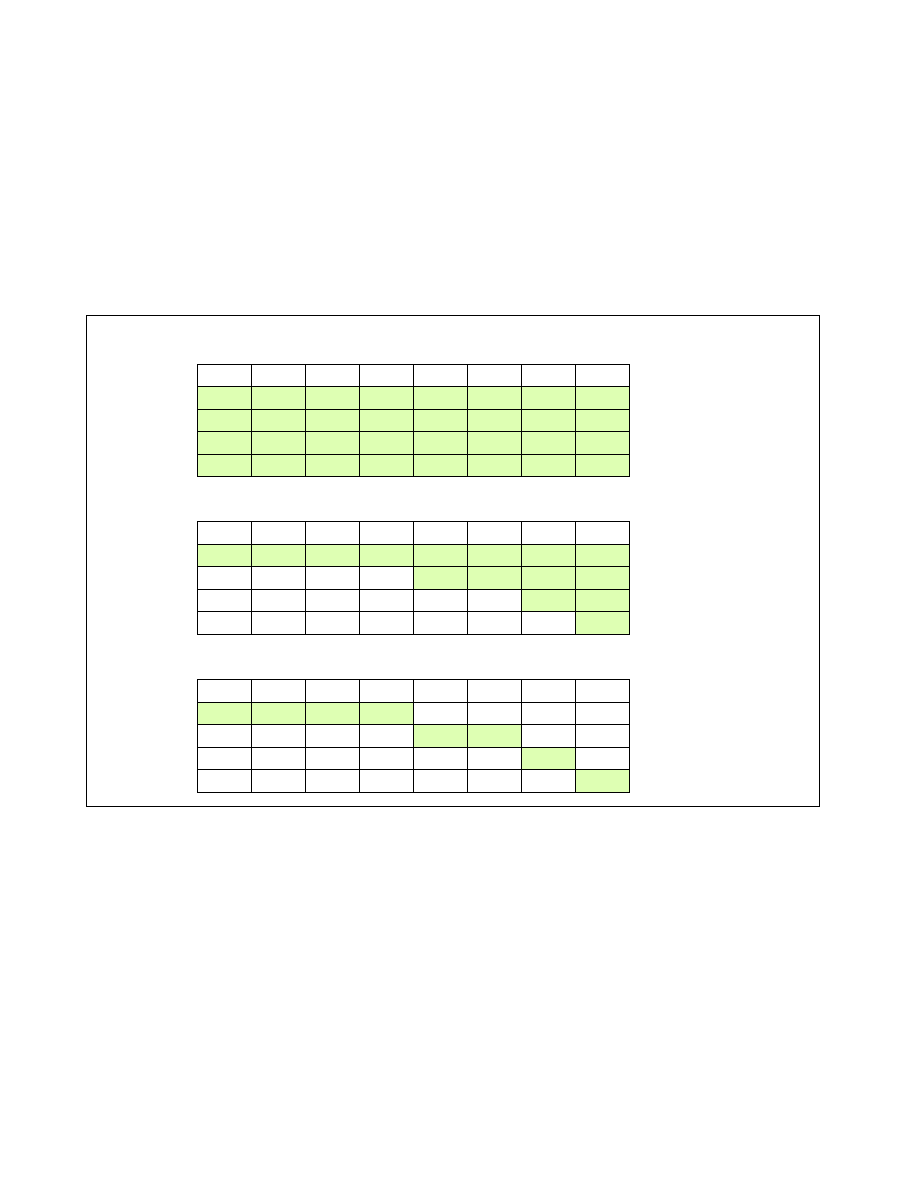
Sample cache capacity bitmasks for a bitlength of 8 are shown in Figure 17-27. Please note that all (and only)
contiguous '1' combinations are allowed (e.g. FFFFH, 0FF0H, 003CH, etc.). Attempts to program a value without
contiguous '1's (including zero) will result in a general protection fault (#GP(0)). It is generally expected that in
way-based implementations, one capacity mask bit corresponds to some number of ways in cache, but the specific
mapping is implementation-dependent. In all cases, a mask bit set to '1' specifies that a particular Class of Service
can allocate into the cache subset represented by that bit. A value of '0' in a mask bit specifies that a Class of
Service cannot allocate into the given cache subset. In general, allocating more cache to a given application is
usually beneficial to its performance.
Figure 17-27 also shows three examples of sets of Cache Capacity Bitmasks. For simplicity these are represented
as 8-bit vectors, though this may vary depending on the implementation and how the mask is mapped to the avail-
able cache capacity. The first example shows the default case where all 4 Classes of Service (the total number of
COS are implementation-dependent) have full access to the cache. The second case shows an overlapped case,
which would allow some lower-priority threads share cache space with the highest priority threads. The third case
Figure 17-27. Examples of Cache Capacity Bitmasks
M7
M6
M5
M4
M3
M2
M1
M0
A
A
A
A
A
A
A
A
A
A
A
A
A
A
A
A
A
A
A
A
A
A
A
A
A
A
A
A
A
A
A
A
COS0
COS1
COS2
COS3
Default Bitmask
M7
M6
M5
M4
M3
M2
M1
M0
A
A
A
A
A
A
A
A
COS0
COS1
COS2
COS3
Isolated Bitmask
M7
M6
M5
M4
M3
M2
M1
M0
A
A
A
A
A
A
A
A
A
A
A
A
A
A
A
COS0
COS1
COS2
COS3
Overlapped Bitmask