Vol. 3B 17-19
DEBUG, BRANCH PROFILE, TSC, AND RESOURCE MONITORING FEATURES
Figures 17-6 shows the structure of a 12-byte branch record in the BTS buffer. The fields in each record are as
follows:
•
Last branch from — Linear address of the instruction from which the branch, interrupt, or exception was
taken.
•
Last branch to — Linear address of the branch target or the first instruction in the interrupt or exception
service routine.
•
Branch predicted — Bit 4 of field indicates whether the branch that was taken was predicted (set) or not
predicted (clear).
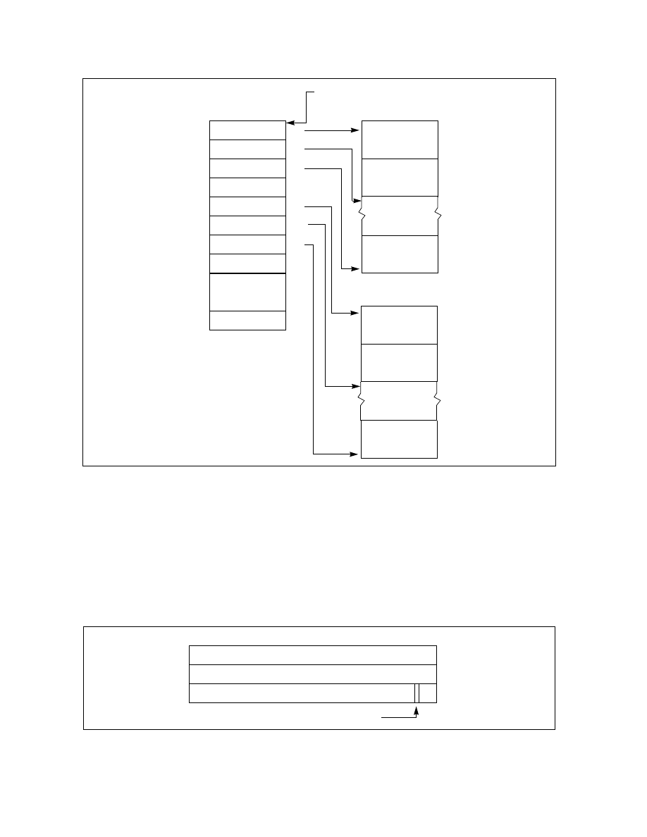
Figure 17-5. DS Save Area
Figure 17-6. 32-bit Branch Trace Record Format
BTS Buffer Base
BTS Index
BTS Absolute
BTS Interrupt
PEBS Absolute
PEBS Interrupt
PEBS
Maximum
Maximum
Threshold
PEBS Index
PEBS Buffer Base
Threshold
Counter Reset
Reserved
0H
4H
8H
CH
10H
14H
18H
1CH
20H
24H
30H
Branch Record 0
Branch Record 1
Branch Record n
PEBS Record 0
PEBS Record 1
PEBS Record n
BTS Buffer
PEBS Buffer
DS Buffer Management Area
IA32_DS_AREA MSR
Last Branch From
Last Branch To
Branch Predicted
0H
4H
8H
0
31
4