Vol. 3B 17-5
DEBUG, BRANCH PROFILE, TSC, AND RESOURCE MONITORING FEATURES
If the corresponding RWn field in register DR7 is 00 (instruction execution), then the LENn field should also be 00.
The effect of using other lengths is undefined. See Section 17.2.5, ÔÇťBreakpoint Field Recognition,ÔÇŁ below.
NOTES
For Pentium
®
4 and Intel
®
Xeon
®
processors with a CPUID signature corresponding to family 15
(model 3, 4, and 6), break point conditions permit specifying 8-byte length on data read/write with
an of encoding 10B in the LENn field.
Encoding 10B is also supported in processors based on Intel Core microarchitecture or enhanced
Intel Core microarchitecture, the respective CPUID signatures corresponding to family 6, model 15,
and family 6, DisplayModel value 23 (see CPUID instruction in Chapter 3, ÔÇťInstruction Set
Reference, A-LÔÇŁ in the Intel┬« 64 and IA-32 Architectures Software DeveloperÔÇÖs Manual, Volume
2A). The Encoding 10B is supported in processors based on Intel
®
AtomÔäó microarchitecture, with
CPUID signature of family 6, DisplayModel value 1CH. The encoding 10B is undefined for other
processors.
17.2.5
Breakpoint Field Recognition
Breakpoint address registers (debug registers DR0 through DR3) and the LENn fields for each breakpoint define a
range of sequential byte addresses for a data or I/O breakpoint. The LENn fields permit specification of a 1-, 2-, 4-
, or 8-byte range, beginning at the linear address specified in the corresponding debug register (DRn). Two-byte
ranges must be aligned on word boundaries; 4-byte ranges must be aligned on doubleword boundaries. I/O
addresses are zero-extended (from 16 to 32 bits, for comparison with the breakpoint address in the selected debug
register). These requirements are enforced by the processor; it uses LENn field bits to mask the lower address bits
in the debug registers. Unaligned data or I/O breakpoint addresses do not yield valid results.
A data breakpoint for reading or writing data is triggered if any of the bytes participating in an access is within the
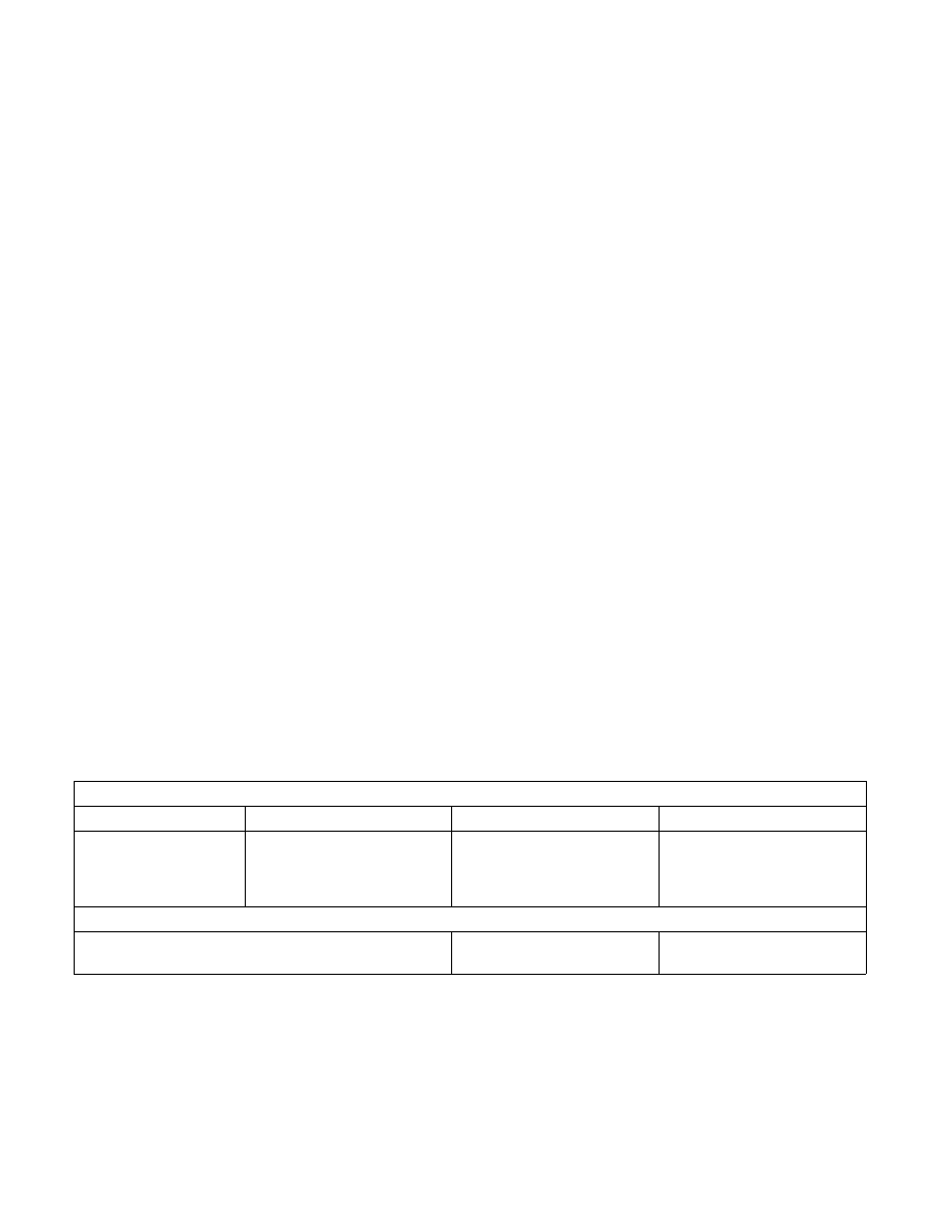
range defined by a breakpoint address register and its LENn field. Table 17-1 provides an example setup of debug
registers and data accesses that would subsequently trap or not trap on the breakpoints.
A data breakpoint for an unaligned operand can be constructed using two breakpoints, where each breakpoint is
byte-aligned and the two breakpoints together cover the operand. The breakpoints generate exceptions only for
the operand, not for neighboring bytes.
Instruction breakpoint addresses must have a length specification of 1 byte (the LENn field is set to 00). Code
breakpoints for other operand sizes are undefined. The processor recognizes an instruction breakpoint address
only when it points to the first byte of an instruction. If the instruction has prefixes, the breakpoint address must
point to the first prefix.
Table 17-1. Breakpoint Examples
Debug Register Setup
Debug Register
R/Wn
Breakpoint Address
LENn
DR0
DR1
DR2
DR3
R/W0 = 11 (Read/Write)
R/W1 = 01 (Write)
R/W2 = 11 (Read/Write)
R/W3 = 01 (Write)
A0001H
A0002H
B0002H
C0000H
LEN0 = 00 (1 byte)
LEN1 = 00 (1 byte)
LEN2 = 01) (2 bytes)
LEN3 = 11 (4 bytes)
Data Accesses
Operation
Address
Access Length
(In Bytes)