Vol. 3B 14-27
POWER AND THERMAL MANAGEMENT
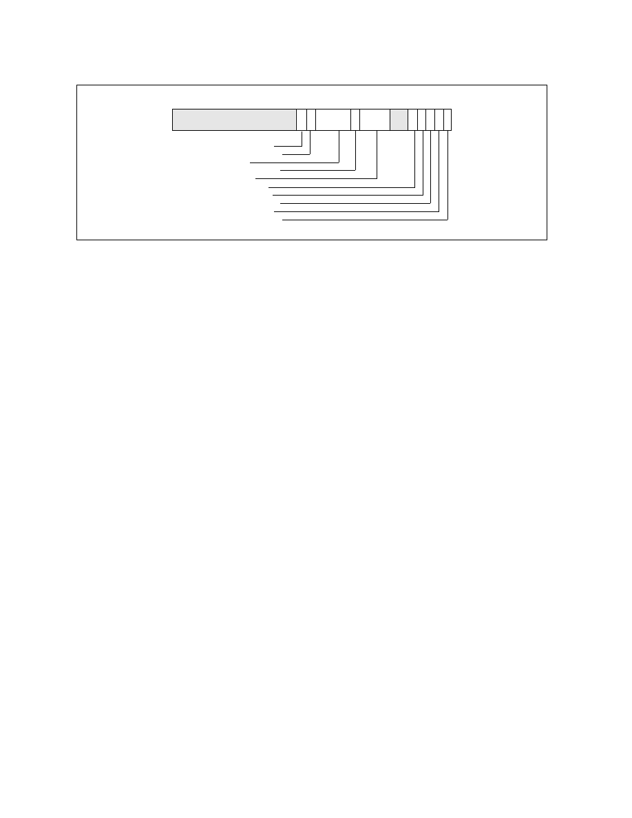
See Figure 14-28 for the layout of IA32_THERM_INTERRUPT MSR. Bit fields include:
•
High-Temperature Interrupt Enable (bit 0, R/W) — This bit allows the BIOS to enable the generation of
an interrupt on the transition from low-temperature to a high-temperature threshold. Bit 0 = 0 (default)
disables interrupts; bit 0 = 1 enables interrupts.
•
Low-Temperature Interrupt Enable (bit 1, R/W) — This bit allows the BIOS to enable the generation of an
interrupt on the transition from high-temperature to a low-temperature (TCC de-activation). Bit 1 = 0 (default)
disables interrupts; bit 1 = 1 enables interrupts.
•
PROCHOT# Interrupt Enable (bit 2, R/W) — This bit allows the BIOS or OS to enable the generation of an
interrupt when PROCHOT# has been asserted by another agent on the platform and the Bidirectional Prochot
feature is enabled. Bit 2 = 0 disables the interrupt; bit 2 = 1 enables the interrupt.
•
FORCEPR# Interrupt Enable (bit 3, R/W) — This bit allows the BIOS or OS to enable the generation of an
interrupt when FORCEPR# has been asserted by another agent on the platform. Bit 3 = 0 disables the
interrupt; bit 3 = 1 enables the interrupt.
•
Critical Temperature Interrupt Enable (bit 4, R/W) — Enables the generation of an interrupt when the
Critical Temperature Detector has detected a critical thermal condition. The recommended response to this
condition is a system shutdown. Bit 4 = 0 disables the interrupt; bit 4 = 1 enables the interrupt.
•
Threshold #1 Value (bits 14:8, R/W) — A temperature threshold, encoded relative to the TCC Activation
temperature (using the same format as the Digital Readout). This threshold is compared against the Digital
Readout and is used to generate the Thermal Threshold #1 Status and Log bits as well as the Threshold #1
thermal interrupt delivery.
•
Threshold #1 Interrupt Enable (bit 15, R/W) — Enables the generation of an interrupt when the actual
temperature crosses the Threshold #1 setting in any direction. Bit 15 = 1 enables the interrupt; bit 15 = 0
disables the interrupt.
•
Threshold #2 Value (bits 22:16, R/W) —A temperature threshold, encoded relative to the TCC Activation
temperature (using the same format as the Digital Readout). This threshold is compared against the Digital
Readout and is used to generate the Thermal Threshold #2 Status and Log bits as well as the Threshold #2
thermal interrupt delivery.
•
Threshold #2 Interrupt Enable (bit 23, R/W) — Enables the generation of an interrupt when the actual
temperature crosses the Threshold #2 setting in any direction. Bit 23 = 1enables the interrupt; bit 23 = 0
disables the interrupt.
•
Power Limit Notification Enable (bit 24, R/W) — Enables the generation of power notification events when
the processor went below OS-requested P-state or OS-requested clock modulation duty cycle. This field is
supported only if CPUID.06H:EAX[bit 4] = 1. Package level power limit notification can be enabled indepen-
dently by IA32_PACKAGE_THERM_INTERRUPT MSR.
Figure 14-28. IA32_THERM_INTERRUPT Register
63
0
Reserved
15
Threshold #2 Interrupt Enable
1
2
3
4
5
8
14
16
22
23
24
Threshold #2 Value
Threshold #1 Interrupt Enable
Threshold #1 Value
Overheat Interrupt Enable
FORCPR# Interrupt Enable
PROCHOT# Interrupt Enable
Low Temp. Interrupt Enable
High Temp. Interrupt Enable
25
Power Limit Notification Enable