14-16 Vol. 3B
POWER AND THERMAL MANAGEMENT
A value of zero in IA32_THREAD_STALL indicates either HDC is not supported or the logical processor never
serviced any forced HDC idle. A non-zero value in IA32_THREAD_STALL indicates the HDC forced-idle residency
times of the logical processor. It also indicates the forced-idle cycles due to HDC that could appear as C0 time to
traditional OS accounting mechanisms (e.g. time-stamping OS idle/exit events).
Software can read IA32_THREAD_STALL irrespective of the state of IA32_PKG_HDC_CTL and IA32_PM_CTL1, as
long as CPUID.06H:EAX[bit 13] = 1.
14.5.4.2 Non-Architectural HDC Residency Counters
Processors that support HDC operation may provide the following model-specific HDC residency counters.
MSR_CORE_HDC_RESIDENCY
Software can track per-core HDC residency using the counter MSR_CORE_HDC_RESIDENCY. This counter incre-
ments when the core is in C3 state or deeper (all logical processors in this core are idle due to either HDC or other
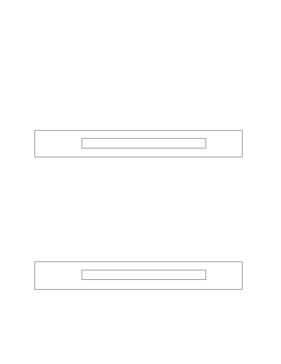
mechanisms) and at least one of the logical processors is in HDC forced idle state. The layout of the
MSR_CORE_HDC_RESIDENCY is shown in Figure 14-15. Each processor core in a package has its own
MSR_CORE_HDC_RESIDENCY MSR. The bit fields are described below:
•
Core_Cx_Duty_Cycle_Cnt (bits 63:0, R/O) — Stores accumulated HDC forced-idle cycle count of this
processor core since last RESET. This counter increments at the same rate of the TSC. The count is updated only
after core C-state exit from a forced idled C-state. At each update, the increment counts cycles when the core
is in a Cx state (all its logical processor are idle) and at least one logical processor in this core was forced into
idle state due to HDC. If CPUID.06H:EAX[bit 13] = 0, attempt to access this MSR will cause a #GP fault. Default
= zero (0).
A value of zero in MSR_CORE_HDC_RESIDENCY indicates either HDC is not supported or this processor core never
serviced any forced HDC idle.
MSR_PKG_HDC_SHALLOW_RESIDENCY
The counter MSR_PKG_HDC_SHALLOW_RESIDENCY allows software to track HDC residency time when the
package is in C2 state, all processor cores in the package are not active and at least one logical processor was
forced into idle state due to HDC. The layout of the MSR_PKG_HDC_SHALLOW_RESIDENCY is shown in
Figure 14-16. There is one MSR_PKG_HDC_SHALLOW_RESIDENCY per package. The bit fields are described
below:
•
Pkg_Duty_Cycle_Cnt (bits 63:0, R/O) — Stores accumulated HDC forced-idle cycle count of this processor
core since last RESET. This counter increments at the same rate of the TSC. Package shallow residency may be
implementation specific. In the initial implementation, the threshold is package C2-state. The count is
updated only after package C2-state exit from a forced idled C-state. At each update, the increment counts
Figure 14-15. MSR_CORE_HDC_RESIDENCY MSR
Figure 14-16. MSR_PKG_HDC_SHALLOW_RESIDENCY MSR
63
0
Core_Cx_duty_cycle_cnt
63
0
Pkg_Duty_cycle_cnt