8-54 Vol. 3A
MULTIPLE-PROCESSOR MANAGEMENT
6. After the BSP has been established, the outstanding BIPIs are received one at a time (at T2, T3, and T4) and
ignored by all processors.
7. When the FIPI is finally received (at T5), only the BSP responds to it. It responds by fetching and executing
BIOS boot-strap code, beginning at the reset vector (physical address FFFF FFF0H).
8. As part of the boot-strap code, the BSP creates an ACPI table and an MP table and adds its initial APIC ID to
these tables as appropriate.
9. At the end of the boot-strap procedure, the BSP broadcasts a SIPI message to all the APs in the system. Here,
the SIPI message contains a vector to the BIOS AP initialization code (at 000V V000H, where VV is the vector
contained in the SIPI message).
10. All APs respond to the SIPI message by racing to a BIOS initialization semaphore. The first one to the
semaphore begins executing the initialization code. (See MP init code for semaphore implementation details.)
As part of the AP initialization procedure, the AP adds its APIC ID number to the ACPI and MP tables as appro-
priate. At the completion of the initialization procedure, the AP executes a CLI instruction (to clear the IF flag in
the EFLAGS register) and halts itself.
11. When each of the APs has gained access to the semaphore and executed the AP initialization code and all
written their APIC IDs into the appropriate places in the ACPI and MP tables, the BSP establishes a count for the
number of processors connected to the system bus, completes executing the BIOS boot-strap code, and then
begins executing operating-system boot-strap and start-up code.
12. While the BSP is executing operating-system boot-strap and start-up code, the APs remain in the halted state.
In this state they will respond only to INITs, NMIs, and SMIs. They will also respond to snoops and to assertions
of the STPCLK# pin.
See Section 8.4.4, “MP Initialization Example,” for an annotated example the use of the MP protocol to boot IA-32
processors in an MP. This code should run on any IA-32 processor that used the MP protocol.
8.11.2.1 Error Detection and Handling During the MP Initialization Protocol
Errors may occur on the APIC bus during the MP initialization phase. These errors may be transient or permanent
and can be caused by a variety of failure mechanisms (for example, broken traces, soft errors during bus usage,
etc.). All serial bus related errors will result in an APIC checksum or acceptance error.
The MP initialization protocol makes the following assumptions regarding errors that occur during initialization:
•
If errors are detected on the APIC bus during execution of the MP initialization protocol, the processors that
detect the errors are shut down.
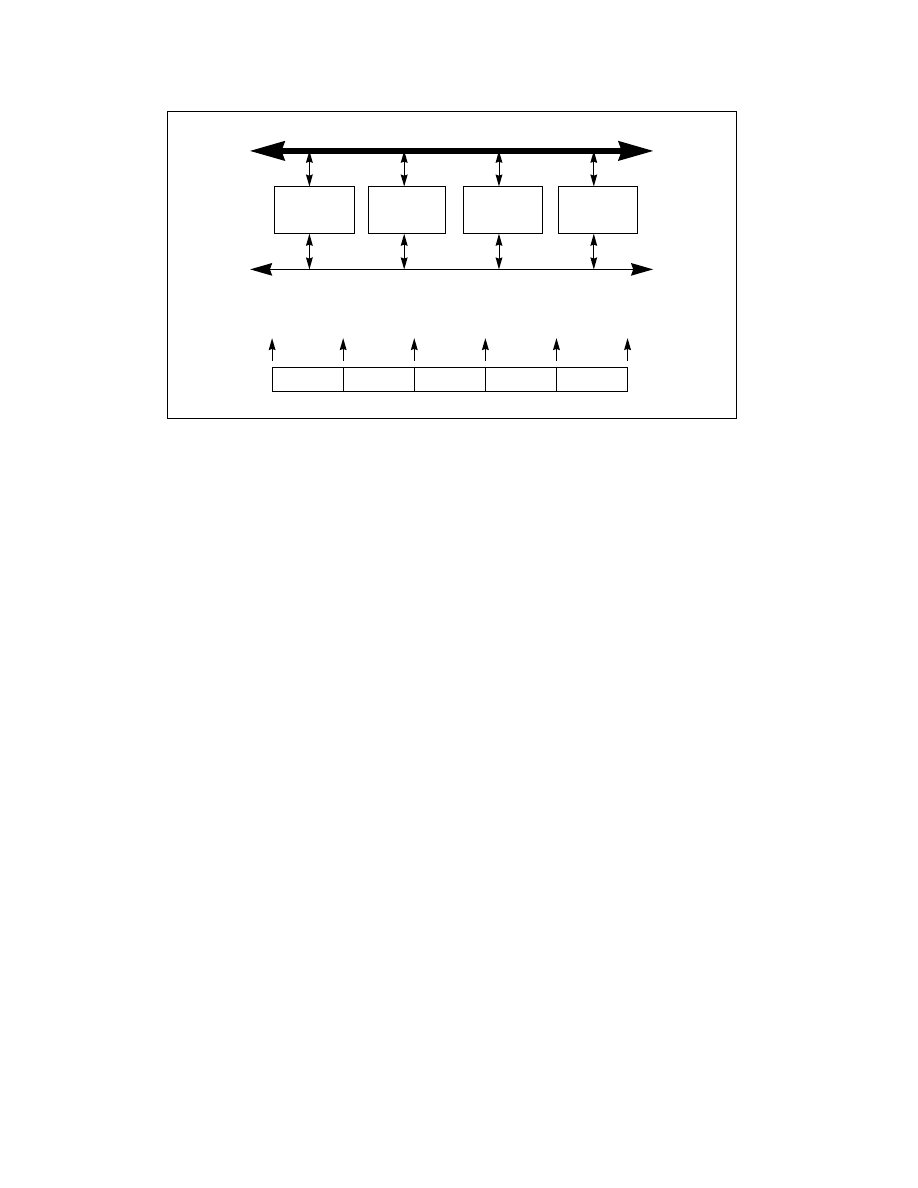
Figure 8-1. MP System With Multiple Pentium III Processors
Pentium III
Processor 0
Pentium III
Processor 1
Pentium III
Processor 2
Pentium III
Processor 3
BIPI.1
BIPI.0
BIPI.3
BIPI.2
FIPI
T0
T1
T2
T3
T4
T5
System (CPU) Bus
APIC Bus
Serial Bus Activity
Processor 1
Becomes BSP