Vol. 3A 6-19
INTERRUPT AND EXCEPTION HANDLING
6.14.5
Interrupt Stack Table
In IA-32e mode, a new interrupt stack table (IST) mechanism is available as an alternative to the modified legacy
stack-switching mechanism described above. This mechanism unconditionally switches stacks when it is enabled.
It can be enabled on an individual interrupt-vector basis using a field in the IDT entry. This means that some inter-
rupt vectors can use the modified legacy mechanism and others can use the IST mechanism.
The IST mechanism is only available in IA-32e mode. It is part of the 64-bit mode TSS. The motivation for the IST
mechanism is to provide a method for specific interrupts (such as NMI, double-fault, and machine-check) to always
execute on a known good stack. In legacy mode, interrupts can use the task-switch mechanism to set up a known-
good stack by accessing the interrupt service routine through a task gate located in the IDT. However, the legacy
task-switch mechanism is not supported in IA-32e mode.
The IST mechanism provides up to seven IST pointers in the TSS. The pointers are referenced by an interrupt-gate
descriptor in the interrupt-descriptor table (IDT); see Figure 6-7. The gate descriptor contains a 3-bit IST index
field that provides an offset into the IST section of the TSS. Using the IST mechanism, the processor loads the
value pointed by an IST pointer into the RSP.
When an interrupt occurs, the new SS selector is forced to NULL and the SS selector’s RPL field is set to the new
CPL. The old SS, RSP, RFLAGS, CS, and RIP are pushed onto the new stack. Interrupt processing then proceeds as
normal. If the IST index is zero, the modified legacy stack-switching mechanism described above is used.
6.15
EXCEPTION AND INTERRUPT REFERENCE
The following sections describe conditions which generate exceptions and interrupts. They are arranged in the
order of vector numbers. The information contained in these sections are as follows:
•
Exception Class — Indicates whether the exception class is a fault, trap, or abort type. Some exceptions can
be either a fault or trap type, depending on when the error condition is detected. (This section is not applicable
to interrupts.)
•
Description — Gives a general description of the purpose of the exception or interrupt type. It also describes
how the processor handles the exception or interrupt.
•
Exception Error Code — Indicates whether an error code is saved for the exception. If one is saved, the
contents of the error code are described. (This section is not applicable to interrupts.)
•
Saved Instruction Pointer — Describes which instruction the saved (or return) instruction pointer points to.
It also indicates whether the pointer can be used to restart a faulting instruction.
•
Program State Change — Describes the effects of the exception or interrupt on the state of the currently
running program or task and the possibilities of restarting the program or task without loss of continuity.
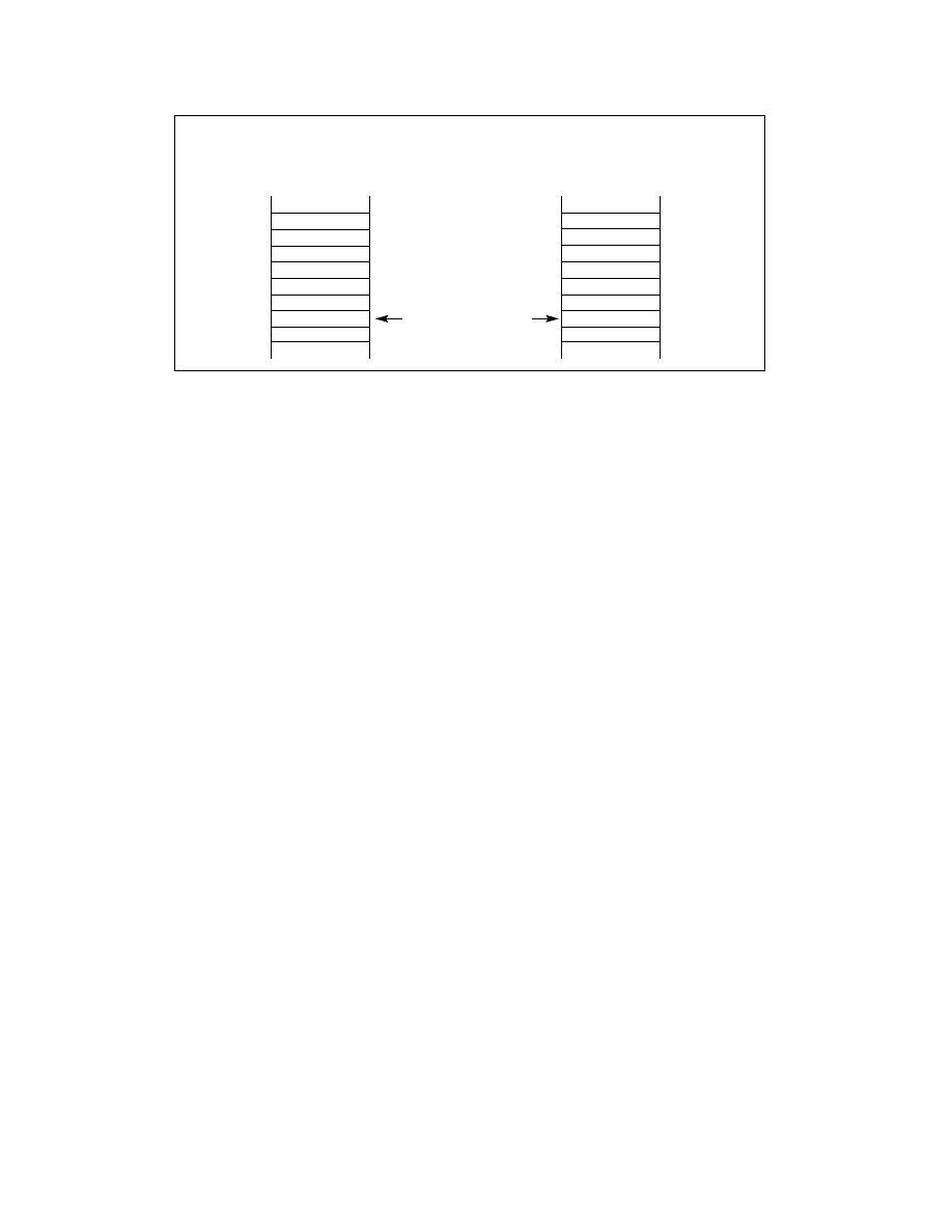
Figure 6-8. IA-32e Mode Stack Usage After Privilege Level Change
CS
Error Code
RFLAGS
RIP
SS
RSP
Stack Usage with
Privilege-Level Change
Handler’s Stack
Stack Pointer After
Transfer to Handler
CS
Error Code
EFLAGS
EIP
SS
ESP
Handler’s Stack
Legacy Mode
IA-32e Mode
0
+4
+8
+12
+16
+20
0
+8
+16
+24
+32
+40