Vol. 3A 6-17
INTERRUPT AND EXCEPTION HANDLING
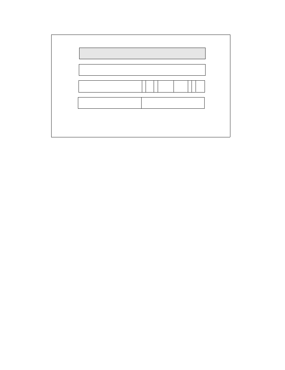
In 64-bit mode, the IDT index is formed by scaling the interrupt vector by 16. The first eight bytes (bytes 7:0) of a
64-bit mode interrupt gate are similar but not identical to legacy 32-bit interrupt gates. The type field (bits 11:8 in
bytes 7:4) is described in Table 3-2. The Interrupt Stack Table (IST) field (bits 4:0 in bytes 7:4) is used by the stack
switching mechanisms described in Section 6.14.5, “Interrupt Stack Table.” Bytes 11:8 hold the upper 32 bits of
the target RIP (interrupt segment offset) in canonical form. A general-protection exception (#GP) is generated if
software attempts to reference an interrupt gate with a target RIP that is not in canonical form.
The target code segment referenced by the interrupt gate must be a 64-bit code segment (CS.L = 1, CS.D = 0). If
the target is not a 64-bit code segment, a general-protection exception (#GP) is generated with the IDT vector
number reported as the error code.
Only 64-bit interrupt and trap gates can be referenced in IA-32e mode (64-bit mode and compatibility mode).
Legacy 32-bit interrupt or trap gate types (0EH or 0FH) are redefined in IA-32e mode as 64-bit interrupt and trap
gate types. No 32-bit interrupt or trap gate type exists in IA-32e mode. If a reference is made to a 16-bit interrupt
or trap gate (06H or 07H), a general-protection exception (#GP(0)) is generated.
6.14.2
64-Bit Mode Stack Frame
In legacy mode, the size of an IDT entry (16 bits or 32 bits) determines the size of interrupt-stack-frame pushes.
SS:ESP is pushed only on a CPL change. In 64-bit mode, the size of interrupt stack-frame pushes is fixed at eight
bytes. This is because only 64-bit mode gates can be referenced. 64-bit mode also pushes SS:RSP unconditionally,
rather than only on a CPL change.
Aside from error codes, pushing SS:RSP unconditionally presents operating systems with a consistent interrupt-
stackframe size across all interrupts. Interrupt service-routine entry points that handle interrupts generated by the
INTn instruction or external INTR# signal can push an additional error code place-holder to maintain consistency.
In legacy mode, the stack pointer may be at any alignment when an interrupt or exception causes a stack frame to
be pushed. This causes the stack frame and succeeding pushes done by an interrupt handler to be at arbitrary
alignments. In IA-32e mode, the RSP is aligned to a 16-byte boundary before pushing the stack frame. The stack
frame itself is aligned on a 16-byte boundary when the interrupt handler is called. The processor can arbitrarily
realign the new RSP on interrupts because the previous (possibly unaligned) RSP is unconditionally saved on the
newly aligned stack. The previous RSP will be automatically restored by a subsequent IRET.
Aligning the stack permits exception and interrupt frames to be aligned on a 16-byte boundary before interrupts
are re-enabled. This allows the stack to be formatted for optimal storage of 16-byte XMM registers, which enables
Figure 6-7. 64-Bit IDT Gate Descriptors
31
16 15
13
14
12
8 7
0
P
Offset 31..16
D
P
L
0
4
31
16 15
0
Segment Selector
Offset 15..0
0
TYPE
Interrupt/Trap Gate
DPL
Offset
P
Selector
Descriptor Privilege Level
Offset to procedure entry point
Segment Present flag
Segment Selector for destination code segment
4
5
0 0 0
31
0
Offset 63..32
8
31
0
12
11
IST
0 0
2
Reserved
IST
Interrupt Stack Table