Vol. 3C 36-23
INTEL® PROCESSOR TRACE
36.2.8
Interaction of Intel® Processor Trace and Other Processor Features
36.2.8.1 Intel® Transactional Synchronization Extensions (Intel® TSX)
The operation of Intel TSX is described in Chapter 14 of the Intel® 64 and IA-32 Architectures Software Devel-
oper’s Manual, Volume 1. For tracing purpose, packet generation does not distinguish between hardware lock
elision (HLE) and restricted transactional memory (RTM), but speculative execution does have impacts on the trace
output. Specifically, packets are generated as instructions complete, even for instructions in a transactional region
that is later aborted. For this reason, debugging software will need indication of the beginning and end of a trans-
actional region; this will allow software to understand when instructions are part of a transactional region and
whether that region has been committed.
To enable this, TSX information is included in a MODE packet leaf. The mode bits in the leaf are:
•
InTX: Set to 1 on an TSX transaction begin, and cleared on transaction commit or abort.
•
TXAbort: Set to 1 only when InTX transitions from 1 to 0 on an abort. Cleared otherwise.
If BranchEn=1, this MODE packet will be sent each time the transaction status changes. See Table 36-10 for
details.
The CurrentIP listed above is the IP of the associated instruction. The TargetIP is the IP of the next instruction to
be executed; for HLE, this is the XACQUIRE lock; for RTM, this is the fallback handler.
Intel PT stores are non-transactional, and thus packet writes are not rolled back on TSX abort.
63:32
OutputOffset
0
The use of this field depends on the value of IA32_RTIT_CTL.ToPA:
0: This is bits 31:0 of the offset pointer into the single, contiguous physical output region.
This value will be added to the IA32_RTIT_OUTPUT_BASE value to form the physical address
at which the next byte of packet output data will be written. This value must be less than or
equal to the MaskOrTableOffset field, otherwise an operational error (Section 36.3.9) will be
signaled when TraceEn is set.
1: This field holds bits 31:0 of the offset pointer into the current ToPA output region. This
value will be added to the output region base field, found in the current ToPA table entry, to
form the physical address at which the next byte of trace output data will be written.
This value must be less than the ToPA entry size, otherwise an operational error (Section
36.3.9) will be signaled when TraceEn is set.
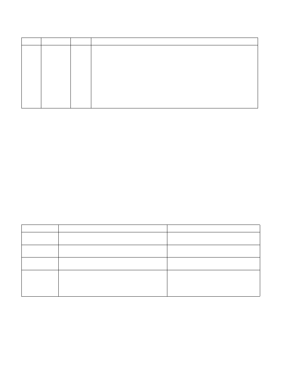
Table 36-10. TSX Packet Scenarios
TSX Event
Instruction
Packets
Transaction Begin Either XBEGIN or XACQUIRE lock (the latter if executed
transactionally)
MODE(TXAbort=0, InTX=1), FUP(CurrentIP)
Transaction
Commit
Either XEND or XRELEASE lock, if transactional execution
ends. This happens only on the outermost commit
MODE(TXAbort=0, InTX=0), FUP(CurrentIP)
Transaction Abort XABORT or other transactional abort
MODE(TXAbort=1, InTX=0), FUP(CurrentIP),
TIP(TargetIP)
Other
One of the following:
• Nested XBEGIN or XACQUIRE lock
• An outer XACQUIRE lock that doesn’t begin a transaction
(InTX not set)
• Non-outermost XEND or XRELEASE lock
None. No change to TSX mode bits for these
cases.
Table 36-9. IA32_RTIT_OUTPUT_MASK_PTRS MSR (Contd.)
Position
Bit Name
At Reset
Bit Description