Vol. 3C 36-11
INTEL® PROCESSOR TRACE
It is important to note that processor updates to the IA32_RTIT_OUTPUT_BASE and
IA32_RTIT_OUTPUT_MASK_PTRS MSRs are asynchronous to instruction execution. Thus, reads of these MSRs
while Intel PT is enabled may return stale values. Like all IA32_RTIT_* MSRs, the values of these MSRs should not
be trusted or saved unless trace packet generation is first disabled by clearing IA32_RTIT_CTL.TraceEn. This
ensures that he output MSR values account for all packets generated to that point, after which the output MSR
values will be frozen until tracing resumes.
1
The processor may cache internally any number of entries from the current table or from tables that it references
(directly or indirectly). If tracing is enabled, the processor may ignore or delay detection of modifications to these
tables. To ensure that table changes are detected by the processor in a predictable manner, software should clear
TraceEn before modifying the current table (or tables that it references) and only then re-enable packet genera-
tion.
Single Output Region ToPA Implementation
The first processor generation to implement Intel PT supports only ToPA configurations with a single ToPA entry
followed by an END entry that points back to the first entry (creating one circular output buffer). Such processors
enumerate CPUID.(EAX=14H,ECX=0):ECX.MENTRY[bit 1] = 0 and CPUID.(EAX=14H,ECX=0):ECX.TOPAOUT[bit
0] = 1.
If CPUID.(EAX=14H,ECX=0):ECX.MENTRY[bit 1] = 0, ToPA tables can hold only one output entry, which must be
followed by an END=1 entry which points back to the base of the table. Hence only one contiguous block can be
used as output.
The lone output entry can have INT or STOP set, but nonetheless must be followed by an END entry as described
above. Note that, if INT=1, the PMI will actually be delivered before the region is filled.
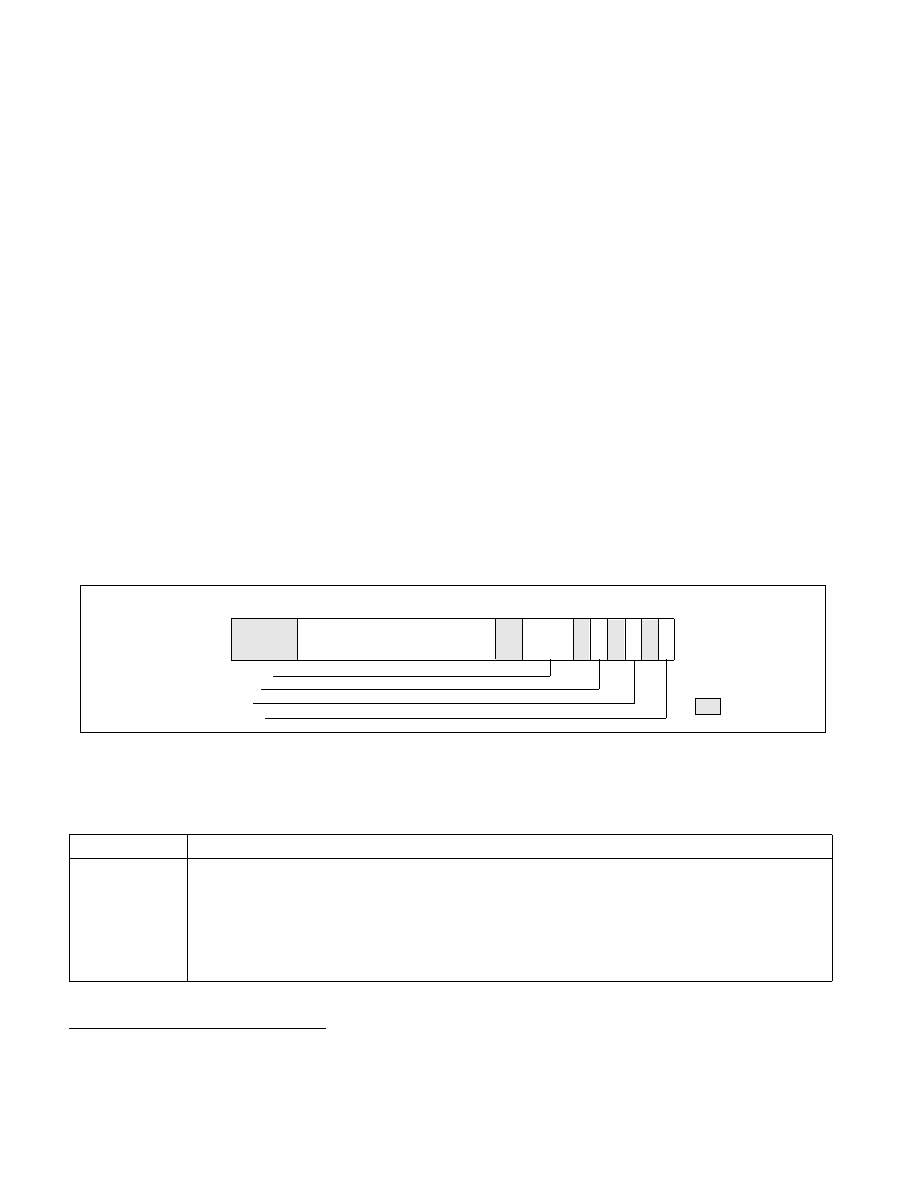
ToPA Table Entry Format
The format of ToPA table entries is shown in Figure 36-2. The size of the address field is determined by the
processor’s physical-address width (MAXPHYADDR) in bits, as reported in CPUID.80000008H:EAX[7:0].
Table 36-3 describes the details of the ToPA table entry fields. If reserved bits are set to 1, an error is signaled.
1. Although WRMSR is a serializing instruction, the execution of WRMSR that forces packet writes by clearing TraceEn does not itself
cause these writes to be globally observed.
Figure 36-2. Layout of ToPA Table Entry
Table 36-3. ToPA Table Entry Fields
ToPA Entry Field
Description
Output Region
Base Physical
Address
If END=0, this is the base physical address of the output region specified by this entry. Note that all regions
must be aligned based on their size. Thus a 2M region must have bits 20:12 clear. If the region is not properly
aligned, an operational error will be signaled when the entry is reached.
If END=1, this is the 4K-aligned base physical address of the next ToPA table (which may be the base of the cur-
rent table, or the first table in the linked list if a circular buffer is desired). If the processor supports only a single
ToPA output region (see above), this address must be the value currently in the IA32_RTIT_OUTPUT_BASE
MSR.
11
9
10
12
MAXPHYADDR–1
9:6 Size
6 5
0
4 : STOP
2 : INT
0 : END
Output Region Base Physical Address
4
1
3
2
Reserved
63