34-12 Vol. 3C
SYSTEM MANAGEMENT MODE
34.7.1
I/O State Implementation
Within the extended SMM state save map, a bit (IO_SMI) is provided that is set only when an SMI is either taken
immediately after a successful I/O instruction or is taken after a successful iteration of a REP I/O instruction (the
successful notion pertains to the processor point of view; not necessarily to the corresponding platform function).
When set, the IO_SMI bit provides a strong indication that the corresponding SMI was synchronous. In this case,
the SMM State Save Map also supplies the port address of the I/O operation. The IO_SMI bit and the I/O Port
Address may be used in conjunction with the information logged by the platform to confirm that the SMI was
indeed synchronous.
The IO_SMI bit by itself is a strong indication, not a guarantee, that the SMI is synchronous. This is because an
asynchronous SMI might coincidentally be taken after an I/O instruction. In such a case, the IO_SMI bit would still
be set in the SMM state save map.
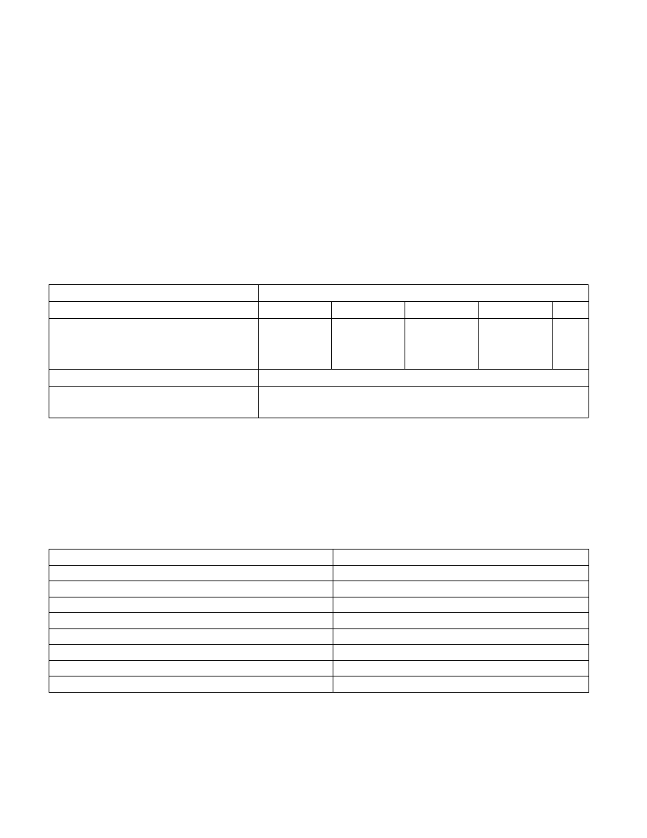
Information characterizing the I/O instruction is saved in two locations in the SMM State Save Map (Table 34-5).
The IO_SMI bit also serves as a valid bit for the rest of the I/O information fields. The contents of these I/O infor-
mation fields are not defined when the IO_SMI bit is not set.
When IO_SMI is set, the other fields may be interpreted as follows:
•
I/O length:
•
001 – Byte
•
010 – Word
•
100 – Dword
•
I/O instruction type (Table 34-6)
Table 34-5. I/O Instruction Information in the SMM State Save Map
State (SMM Rev. ID: 30004H or higher)
Format
31
16
15
8
7
4
3
1
0
I/0 State Field
SMRAM offset 7FA4
I/O P
ort
Re
se
rv
ed
I/O T
yp
e
I/O L
en
gt
h
IO
_S
M
I
31
0
I/O Memory Address Field
SMRAM offset 7FA0
I/O Memory Address
Table 34-6. I/O Instruction Type Encodings
Instruction
Encoding
IN Immediate
1001
IN DX
0001
OUT Immediate
1000
OUT DX
0000
INS
0011
OUTS
0010
REP INS
0111
REP OUTS
0110