Vol. 3A 4-3
PAGING
Because it is used only if IA32_EFER.LME = 1, IA-32e paging is used only in IA-32e mode. (In fact, it is the use of
IA-32e paging that defines IA-32e mode.) IA-32e mode has two sub-modes:
•
Compatibility mode. This mode uses only 32-bit linear addresses. IA-32e paging treats bits 47:32 of such an
address as all 0.
•
64-bit mode. While this mode produces 64-bit linear addresses, the processor ensures that bits 63:47 of such
an address are identical.
1
IA-32e paging does not use bits 63:48 of such addresses.
4.1.2 Paging-Mode
Enabling
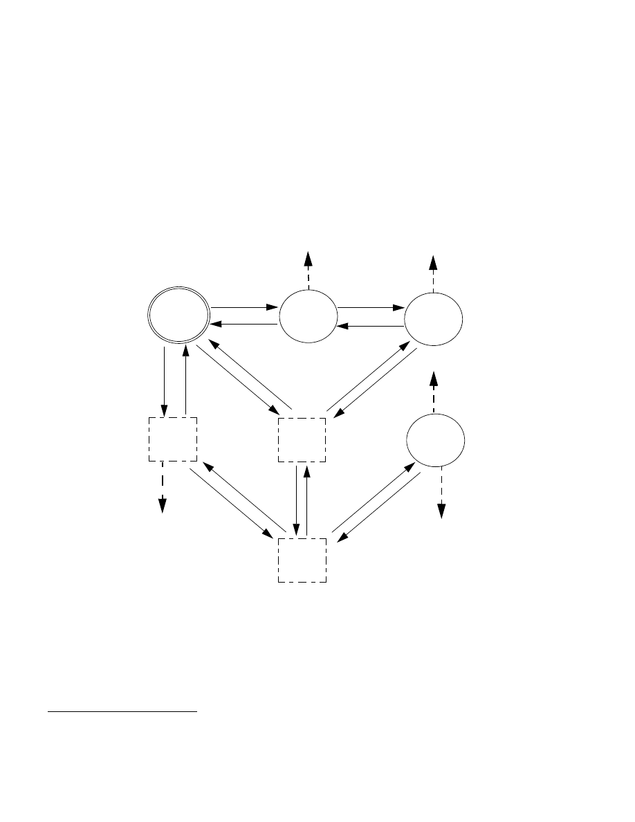
If CR0.PG = 1, a logical processor is in one of three paging modes, depending on the values of CR4.PAE and
IA32_EFER.LME. Figure 4-1 illustrates how software can enable these modes and make transitions between them.
The following items identify certain limitations and other details:
•
IA32_EFER.LME cannot be modified while paging is enabled (CR0.PG = 1). Attempts to do so using WRMSR
cause a general-protection exception (#GP(0)).
•
Paging cannot be enabled (by setting CR0.PG to 1) while CR4.PAE = 0 and IA32_EFER.LME = 1. Attempts to do
so using MOV to CR0 cause a general-protection exception (#GP(0)).
1. Such an address is called canonical. Use of a non-canonical linear address in 64-bit mode produces a general-protection exception
(#GP(0)); the processor does not attempt to translate non-canonical linear addresses using IA-32e paging.
Figure 4-1. Enabling and Changing Paging Modes
PG = 1
No Paging
PAE Paging
PAE = 1
LME = 0
PG = 0
PAE = 0
LME = 0
32-bit Paging
PG = 1
PAE = 0
LME = 0
PG = 0
PAE = 0
LME = 1
Set PG
Set PAE
Clear PAE
Clear PG
No Paging
PG = 0
PAE = 1
LME = 0
No Paging
PG = 1
IA-32e Paging
PAE = 1
LME = 1
Cle
ar LME
Se
tr L
M
E
PG = 0
PAE = 1
LME = 1
No Paging
Clear PAE
Set PAE
Clear PG
Set PG
Set PAE
Clear PAE
Se
tr LM
E
Cle
ar LME
Clear PG
Set PG
#GP
Set LME
#GP
Set LME
#GP
Set PG
Clear PAE
#GP
Cl
ear
LM
E
#GP