2-36 Vol. 2A
INSTRUCTION FORMAT
•
EVEX is a 4-Byte prefix (the first byte must be 62H); VEX is either a 2-Byte (C5H is the first byte) or 3-Byte
(C4H is the first byte) prefix.
•
EVEX prefix can encode 32 vector registers (XMM/YMM/ZMM) in 64-bit mode.
•
EVEX prefix can encode an opmask register for conditional processing or selection control in EVEX-encoded
vector instructions. Opmask instructions, whose source/destination operands are opmask registers and treat
the content of an opmask register as a single value, are encoded using the VEX prefix.
•
EVEX memory addressing with disp8 form uses a compressed disp8 encoding scheme to improve the encoding
density of the instruction byte stream.
•
EVEX prefix can encode functionality that are specific to instruction classes (e.g., packed instruction with
“load+op” semantic can support embedded broadcast functionality, floating-point instruction with rounding
semantic can support static rounding functionality, floating-point instruction with non-rounding arithmetic
semantic can support “suppress all exceptions” functionality).
2.6.1
Instruction Format and EVEX
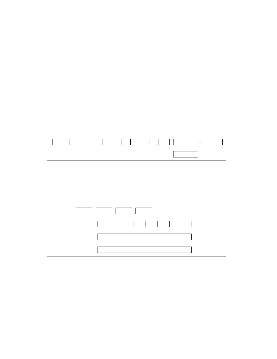
The placement of the EVEX prefix in an IA instruction is represented in Figure 2-10.
The EVEX prefix is a 4-byte prefix, with the first two bytes derived from unused encoding form of the 32-bit-mode-
only BOUND instruction. The layout of the EVEX prefix is shown in Figure 2-11. The first byte must be 62H, followed
by three payload bytes, denoted as P0, P1, and P2 individually or collectively as P[23:0] (see Figure 2-11).
Figure 2-10. AVX-512 Instruction Format and the EVEX Prefix
Figure 2-11. Bit Field Layout of the EVEX Prefix
[Immediate]
[Prefixes]
[Disp32]
[SIB]
ModR/M
Opcode
EVEX
# of bytes:
4
1
1
1
4
1
[Disp8*N]
1
EVEX
62H
P0
P1
P2
P0
7
6
5
4
3
2
0
1
R
X
B
R’
0
0
m
m
P1
7
6
5
4
3
2
0
1
W
v
v
v
v
1
p
p
P2
7
6
5
4
3
2
0
1
z
L’
L
b
V’
a
a
a
P[7:0]
P[15:8]
P[23:16]