INSTRUCTION SET REFERENCE, A-L
Vol. 2A 3-3
3.1.1.2
Opcode Column in the Instruction Summary Table (Instructions with VEX prefix)
In the Instruction Summary Table, the Opcode column presents each instruction encoded using the VEX prefix in
following form (including the modR/M byte if applicable, the immediate byte if applicable):
VEX.[NDS].[128,256].[66,F2,F3].0F/0F3A/0F38.[W0,W1] opcode [/r] [/ib,/is4]
•
VEX — Indicates the presence of the VEX prefix is required. The VEX prefix can be encoded using the three-
byte form (the first byte is C4H), or using the two-byte form (the first byte is C5H). The two-byte form of VEX
only applies to those instructions that do not require the following fields to be encoded: VEX.mmmmm, VEX.W,
VEX.X, VEX.B. Refer to Section 2.3 for more detail on the VEX prefix.
The encoding of various sub-fields of the VEX prefix is described using the following notations:
— NDS, NDD, DDS: Specifies that VEX.vvvv field is valid for the encoding of a register operand:
•
VEX.NDS: VEX.vvvv encodes the first source register in an instruction syntax where the content of
source registers will be preserved.
•
VEX.NDD: VEX.vvvv encodes the destination register that cannot be encoded by ModR/M:reg field.
•
VEX.DDS: VEX.vvvv encodes the second source register in a three-operand instruction syntax where
the content of first source register will be overwritten by the result.
•
If none of NDS, NDD, and DDS is present, VEX.vvvv must be 1111b (i.e. VEX.vvvv does not encode an
operand). The VEX.vvvv field can be encoded using either the 2-byte or 3-byte form of the VEX prefix.
— 128,256: VEX.L field can be 0 (denoted by VEX.128 or VEX.LZ) or 1 (denoted by VEX.256). The VEX.L field
can be encoded using either the 2-byte or 3-byte form of the VEX prefix. The presence of the notation
VEX.256 or VEX.128 in the opcode column should be interpreted as follows:
•
If VEX.256 is present in the opcode column: The semantics of the instruction must be encoded with
VEX.L = 1. An attempt to encode this instruction with VEX.L= 0 can result in one of two situations: (a)
if VEX.128 version is defined, the processor will behave according to the defined VEX.128 behavior; (b)
an #UD occurs if there is no VEX.128 version defined.
•
If VEX.128 is present in the opcode column but there is no VEX.256 version defined for the same
opcode byte: Two situations apply: (a) For VEX-encoded, 128-bit SIMD integer instructions, software
must encode the instruction with VEX.L = 0. The processor will treat the opcode byte encoded with
VEX.L= 1 by causing an #UD exception; (b) For VEX-encoded, 128-bit packed floating-point instruc-
tions, software must encode the instruction with VEX.L = 0. The processor will treat the opcode byte
encoded with VEX.L= 1 by causing an #UD exception (e.g. VMOVLPS).
•
If VEX.LIG is present in the opcode column: The VEX.L value is ignored. This generally applies to VEX-
encoded scalar SIMD floating-point instructions. Scalar SIMD floating-point instruction can be distin-
guished from the mnemonic of the instruction. Generally, the last two letters of the instruction
mnemonic would be either “SS“, “SD“, or “SI“ for SIMD floating-point conversion instructions.
•
If VEX.LZ is present in the opcode column: The VEX.L must be encoded to be 0B, an #UD occurs if
VEX.L is not zero.
R11L
Yes
3
R11W
Yes
3
R11D
Yes
3
R11
Yes
3
R12L
Yes
4
R12W
Yes
4
R12D
Yes
4
R12
Yes
4
R13L
Yes
5
R13W
Yes
5
R13D
Yes
5
R13
Yes
5
R14L
Yes
6
R14W
Yes
6
R14D
Yes
6
R14
Yes
6
R15L
Yes
7
R15W
Yes
7
R15D
Yes
7
R15
Yes
7
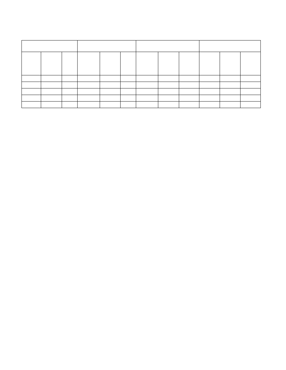
Table 3-1. Register Codes Associated With +rb, +rw, +rd, +ro (Contd.)
byte register
word register
dword register
quadword register
(64-Bit Mode only)
Re
gi
st
er
RE
X
.B
Re
g
Fi
el
d
Re
gi
st
er
RE
X
.B
Re
g
Fi
el
d
Re
gi
st
er
RE
X
.B
Re
g
Fi
el
d
Re
gi
st
er
RE
X
.B
Re
g
Fi
el
d