2-24 Vol. 3A
SYSTEM ARCHITECTURE OVERVIEW
The INVLPG (invalidate TLB entry) instruction invalidates (flushes) the TLB entry for a specified page.
2.8.5
Controlling the Processor
The HLT (halt processor) instruction stops the processor until an enabled interrupt (such as NMI or SMI, which are
normally enabled), a debug exception, the BINIT# signal, the INIT# signal, or the RESET# signal is received. The
processor generates a special bus cycle to indicate that the halt mode has been entered.
Hardware may respond to this signal in a number of ways. An indicator light on the front panel may be turned on.
An NMI interrupt for recording diagnostic information may be generated. Reset initialization may be invoked (note
that the BINIT# pin was introduced with the Pentium Pro processor). If any non-wake events are pending during
shutdown, they will be handled after the wake event from shutdown is processed (for example, A20M# interrupts).
The LOCK prefix invokes a locked (atomic) read-modify-write operation when modifying a memory operand. This
mechanism is used to allow reliable communications between processors in multiprocessor systems, as described
below:
•
In the Pentium processor and earlier IA-32 processors, the LOCK prefix causes the processor to assert the
LOCK# signal during the instruction. This always causes an explicit bus lock to occur.
•
In the Pentium 4, Intel Xeon, and P6 family processors, the locking operation is handled with either a cache lock
or bus lock. If a memory access is cacheable and affects only a single cache line, a cache lock is invoked and
the system bus and the actual memory location in system memory are not locked during the operation. Here,
other Pentium 4, Intel Xeon, or P6 family processors on the bus write-back any modified data and invalidate
their caches as necessary to maintain system memory coherency. If the memory access is not cacheable
and/or it crosses a cache line boundary, the processor’s LOCK# signal is asserted and the processor does not
respond to requests for bus control during the locked operation.
The RSM (return from SMM) instruction restores the processor (from a context dump) to the state it was in prior to
a system management mode (SMM) interrupt.
2.8.6
Reading Performance-Monitoring and Time-Stamp Counters
The RDPMC (read performance-monitoring counter) and RDTSC (read time-stamp counter) instructions allow
application programs to read the processor’s performance-monitoring and time-stamp counters, respectively.
Processors based on Intel NetBurst
®
microarchitecture have eighteen 40-bit performance-monitoring counters; P6
family processors have two 40-bit counters. Intel
®
Atom™ processors and most of the processors based on the
Intel Core microarchitecture support two types of performance monitoring counters: programmable performance
counters similar to those available in the P6 family, and three fixed-function performance monitoring counters.
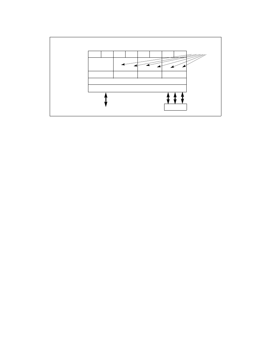
Figure 2-10. WBINVD Invalidation of Shared and Non-Shared Cache Hierarchy
Logical Processors
L1 & L2 Cache
LP0
LP5
QPI
LP1
LP2
LP3
LP4
LP6
LP7
Execution Engine
L3 Cache
Uncore
DDR3
Written back
Written back and Invalidated
Not Written back and
not Invalidated
& Invalidated