2-12 Vol. 3A
SYSTEM ARCHITECTURE OVERVIEW
2.4.1
Global Descriptor Table Register (GDTR)
The GDTR register holds the base address (32 bits in protected mode; 64 bits in IA-32e mode) and the 16-bit table
limit for the GDT. The base address specifies the linear address of byte 0 of the GDT; the table limit specifies the
number of bytes in the table.
The LGDT and SGDT instructions load and store the GDTR register, respectively. On power up or reset of the
processor, the base address is set to the default value of 0 and the limit is set to 0FFFFH. A new base address must
be loaded into the GDTR as part of the processor initialization process for protected-mode operation.
See also: Section 3.5.1, “Segment Descriptor Tables.”
2.4.2
Local Descriptor Table Register (LDTR)
The LDTR register holds the 16-bit segment selector, base address (32 bits in protected mode; 64 bits in IA-32e
mode), segment limit, and descriptor attributes for the LDT. The base address specifies the linear address of byte
0 of the LDT segment; the segment limit specifies the number of bytes in the segment. See also: Section 3.5.1,
“Segment Descriptor Tables.”
The LLDT and SLDT instructions load and store the segment selector part of the LDTR register, respectively. The
segment that contains the LDT must have a segment descriptor in the GDT. When the LLDT instruction loads a
segment selector in the LDTR: the base address, limit, and descriptor attributes from the LDT descriptor are auto-
matically loaded in the LDTR.
When a task switch occurs, the LDTR is automatically loaded with the segment selector and descriptor for the LDT
for the new task. The contents of the LDTR are not automatically saved prior to writing the new LDT information
into the register.
On power up or reset of the processor, the segment selector and base address are set to the default value of 0 and
the limit is set to 0FFFFH.
2.4.3
IDTR Interrupt Descriptor Table Register
The IDTR register holds the base address (32 bits in protected mode; 64 bits in IA-32e mode) and 16-bit table limit
for the IDT. The base address specifies the linear address of byte 0 of the IDT; the table limit specifies the number
of bytes in the table. The LIDT and SIDT instructions load and store the IDTR register, respectively. On power up or
reset of the processor, the base address is set to the default value of 0 and the limit is set to 0FFFFH. The base
address and limit in the register can then be changed as part of the processor initialization process.
See also: Section 6.10, “Interrupt Descriptor Table (IDT).”
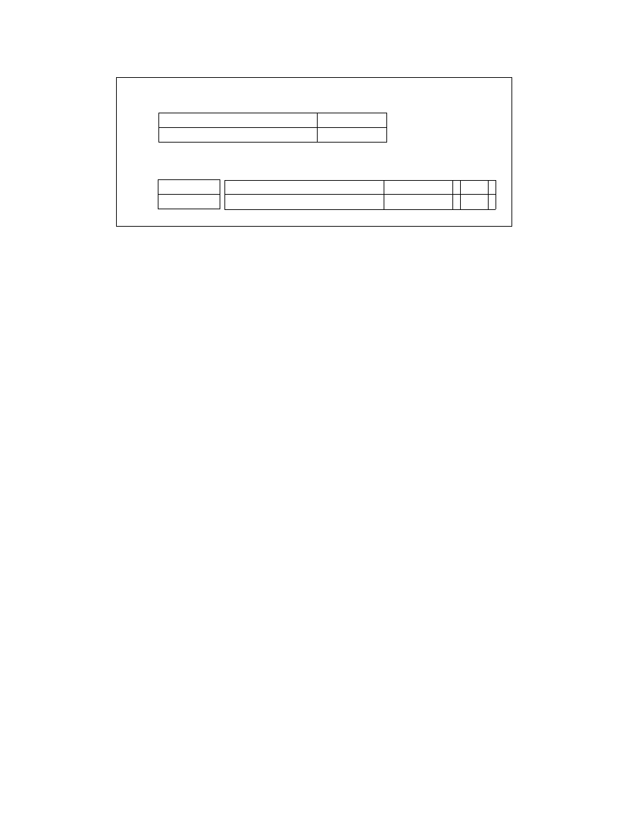
Figure 2-6. Memory Management Registers
0
47(79)
GDTR
IDTR
System Table Registers
32(64)-bit Linear Base Address
16-Bit Table Limit
15
16
32(64)-bit Linear Base Address
0
Task
LDTR
System Segment
Seg. Sel.
15
Seg. Sel.
Segment Descriptor Registers (Automatically Loaded)
32(64)-bit Linear Base Address
Segment Limit
Attributes
Registers
32(64)-bit Linear Base Address
Segment Limit
Register
16-Bit Table Limit