18-38 Vol. 3B
PERFORMANCE MONITORING
•
PEBS Interrupt Threshold: This field specifies the threshold value to trigger a performance interrupt and
notify software that the PEBS buffer is nearly full. This field is programmed with the linear address of the first
byte of the PEBS record within the PEBS buffer that represents the threshold record. After the processor writes
a PEBS record and updates PEBS Index, if the PEBS Index reaches the threshold value of this field, the
processor will generate a performance interrupt. This is the same interrupt that is generated by a performance
counter overflow, as programmed in the Performance Monitoring Counters vector in the Local Vector Table of
the Local APIC. When a performance interrupt due to PEBS buffer full is generated, the
IA32_PERF_GLOBAL_STATUS.PEBS_Ovf bit will be set.
•
PEBS CounterX Reset: This field allows software to set up PEBS counter overflow condition to occur at a rate
useful for profiling workload, thereby generating multiple PEBS records to facilitate characterizing the profile
the execution of test code. After each PEBS record is written, the processor checks each counter to see if it
overflowed and was enabled for PEBS (the corresponding bit in IA32_PEBS_ENABLED was set). If these
conditions are met, then the reset value for each overflowed counter is loaded from the DS Buffer Management
Area. For example, if counter IA32_PMC0 caused a PEBS record to be written, then the value of “PEBS Counter
0 Reset” would be written to counter IA32_PMC0. If a counter is not enabled for PEBS, its value will not be
modified by the PEBS assist.
Performance Counter Prioritization
Performance monitoring interrupts are triggered by a counter transitioning from maximum count to zero (assuming
IA32_PerfEvtSelX.INT is set). This same transition will cause PEBS hardware to arm, but not trigger. PEBS hard-
ware triggers upon detection of the first PEBS event after the PEBS hardware has been armed (a 0 to 1 transition
of the counter). At this point, a PEBS assist will be undertaken by the processor.
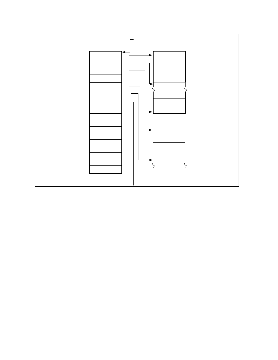
Figure 18-22. PEBS Programming Environment
BTS Buffer Base
BTS Index
BTS Absolute
BTS Interrupt
PEBS Absolute
PEBS Interrupt
PEBS
Maximum
Maximum
Threshold
PEBS Index
PEBS Buffer Base
Threshold
Counter0 Reset
Reserved
0H
8H
10H
18H
20H
28H
30H
38H
40H
48H
50H
Branch Record 0
Branch Record 1
Branch Record n
PEBS Record 0
PEBS Record 1
PEBS Record n
BTS Buffer
PEBS Buffer
DS Buffer Management Area
IA32_DS_AREA MSR
58H
60H
PEBS
Counter1 Reset
PEBS
Counter2 Reset
PEBS
Counter3 Reset