Vol. 3B 17-7
DEBUG, BRANCH PROFILE, TSC, AND RESOURCE MONITORING FEATURES
See also: Chapter 6, “Interrupt 1—Debug Exception (#DB),” in the Intel® 64 and IA-32 Architectures Software
Developer’s Manual, Volume 3A.
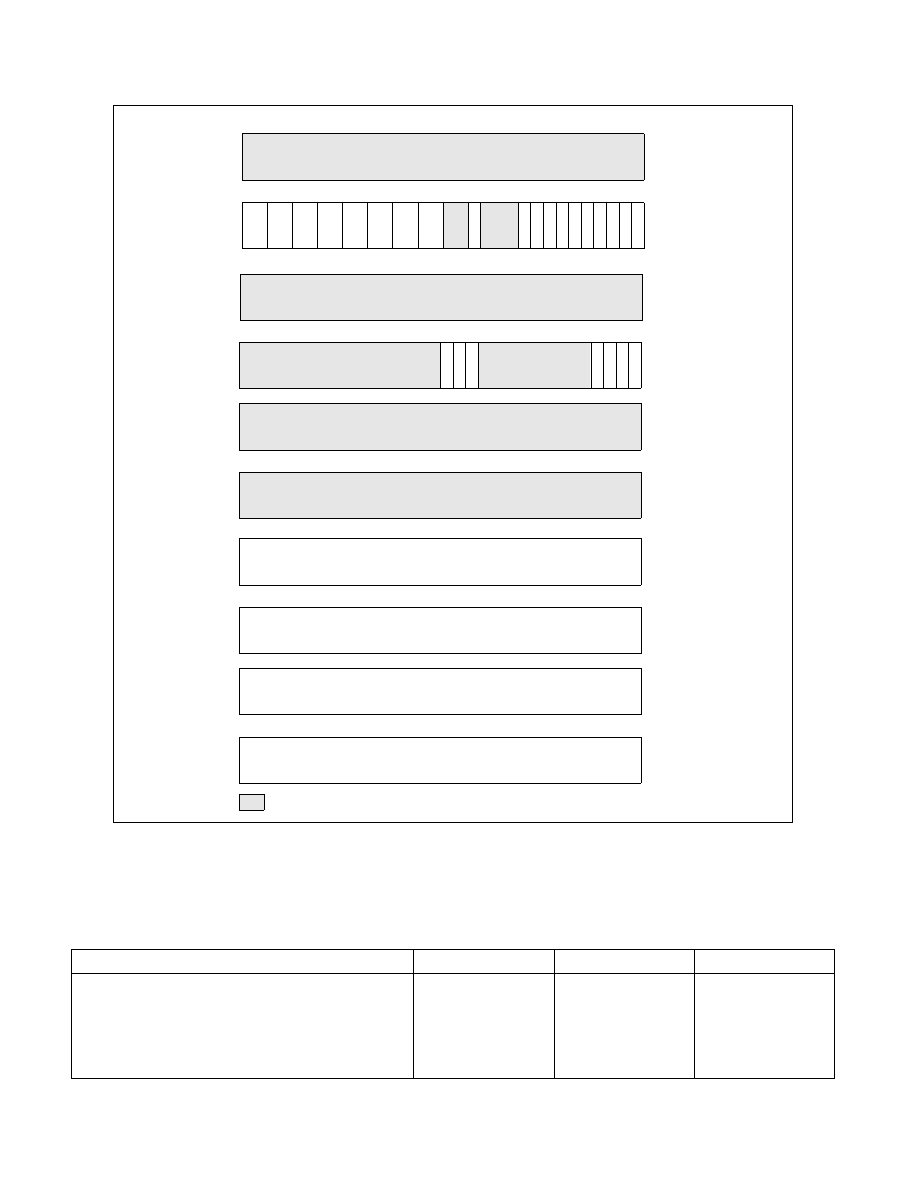
Figure 17-2. DR6/DR7 Layout on Processors Supporting Intel® 64 Architecture
Table 17-2. Debug Exception Conditions
Debug or Breakpoint Condition
DR6 Flags Tested
DR7 Flags Tested
Exception Class
Single-step trap
BS = 1
Trap
Instruction breakpoint, at addresses defined by DRn and
LENn
Bn = 1 and
(Gn or Ln = 1)
R/Wn = 0
Fault
Data write breakpoint, at addresses defined by DRn and
LENn
Bn = 1 and
(Gn or Ln = 1)
R/Wn = 1
Trap
31
24 23 22 21 20 19
16 15
13
14
12 11
8 7
0
DR7
L
Reserved
0
1
2
3
4
5
6
9
10
17
18
25
26
27
28
29
30
G
0
L
1
L
2
L
3
G
3
L
E
G
E
G
2
G
1
G
D
R/W
0
LEN
0
R/W
1
LEN
1
R/W
2
LEN
2
R/W
3
LEN
3
31
16 15
13
14
12 11
8 7
0
DR6
B
0
1
2
3
4
5
6
9
10
B
1
B
2
B
3
0 1 1 1 1 1 1 1 1 1
B
D
B
S
B
T
63
32
63
32
DR6
DR7
0 0
0 0 1
Reserved (set to 1)
63
0
DR3
Breakpoint 3 Linear Address
63
0
DR2
Breakpoint 2 Linear Address
63
0
DR1
Breakpoint 1 Linear Address
63
0
DR0
Breakpoint 0 Linear Address
63
0
DR5
63
0
DR4