14-18 Vol. 3B
POWER AND THERMAL MANAGEMENT
14.5.5
MPERF and APERF Counters Under HDC
HDC operation can be thought of as an average effective frequency drop due to all or some of the Logical Proces-
sors enter an idle state period.
By default, the IA32_MPERF counter counts during forced idle periods as if the logical processor was active. The
IA32_APERF counter does not count during forced idle state. This counting convention allows the OS to compute
the average effective frequency of the Logical Processor between the last MWAIT exit and the next MWAIT entry
(OS visible C0) by ΔACNT/ΔMCNT * TSC Frequency.
14.6
MWAIT EXTENSIONS FOR ADVANCED POWER MANAGEMENT
IA-32 processors may support a number of C-states
1
that reduce power consumption for inactive states. Intel Core
Solo and Intel Core Duo processors support both deeper C-state and MWAIT extensions that can be used by OS to
implement power management policy.
Software should use CPUID to discover if a target processor supports the enumeration of MWAIT extensions. If
CPUID.05H.ECX[Bit 0] = 1, the target processor supports MWAIT extensions and their enumeration (see Chapter
4, “Instruction Set Reference, M-U,” of Intel® 64 and IA-32 Architectures Software Developer’s Manual, Volume
2B).
If CPUID.05H.ECX[Bit 1] = 1, the target processor supports using interrupts as break-events for MWAIT, even
when interrupts are disabled. Use this feature to measure C-state residency as follows:
•
Software can write to bit 0 in the MWAIT Extensions register (ECX) when issuing an MWAIT to enter into a
processor-specific C-state or sub C-state.
•
When a processor comes out of an inactive C-state or sub C-state, software can read a timestamp before an
interrupt service routine (ISR) is potentially executed.
CPUID.05H.EDX allows software to enumerate processor-specific C-states and sub C-states available for use with
MWAIT extensions. IA-32 processors may support more than one C-state of a given C-state type. These are called
sub C-states. Numerically higher C-state have higher power savings and latency (upon entering and exiting) than
lower-numbered C-state.
At CPL = 0, system software can specify desired C-state and sub C-state by using the MWAIT hints register (EAX).
Processors will not go to C-state and sub C-state deeper than what is specified by the hint register. If CPL > 0 and
if MONITOR/MWAIT is supported at CPL > 0, the processor will only enter C1-state (regardless of the C-state
request in the hints register).
Executing MWAIT generates an exception on processors operating at a privilege level where MONITOR/MWAIT are
not supported.
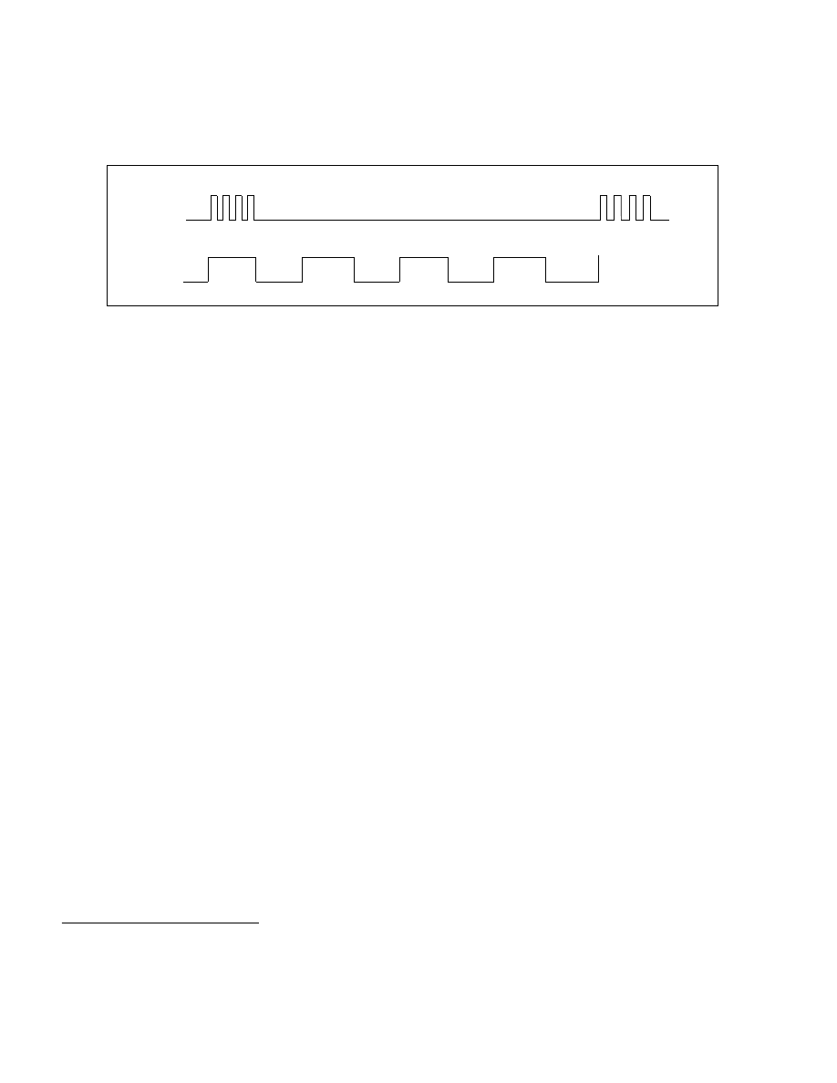
Figure 14-19. Example of Effective Frequency Reduction and Forced Idle Period of HDC
1. The processor-specific C-states defined in MWAIT extensions can map to ACPI defined C-state types (C0, C1, C2, C3). The mapping
relationship depends on the definition of a C-state by processor implementation and is exposed to OSPM by the BIOS using the ACPI
defined _CST table.
1600 MHz: 25% Utilization /75% Forced Idle
Effective Frequency @ 100% Utilization: 400 MHz