35-322 Vol. 3C
MODEL-SPECIFIC REGISTERS (MSRS)
21: 20
Symmetric Arbitration ID (R)
25:22
Clock Frequency Ratio (R)
26
Low Power Mode Enable (R/W)
27
Clock Frequency Ratio
63:28
Reserved.
1
33H
51
TEST_CTL
Test Control Register
29:0
Reserved.
30
Streaming Buffer Disable
31
Disable LOCK#
Assertion for split locked access.
79H
121
BIOS_UPDT_TRIG
BIOS Update Trigger Register.
88H
136
BBL_CR_D0[63:0]
Chunk 0 data register D[63:0]: used to write to and read from the L2
89H
137
BBL_CR_D1[63:0]
Chunk 1 data register D[63:0]: used to write to and read from the L2
8AH
138
BBL_CR_D2[63:0]
Chunk 2 data register D[63:0]: used to write to and read from the L2
8BH
139
BIOS_SIGN/BBL_CR_D3[63:0]
BIOS Update Signature Register or Chunk 3 data register D[63:0]
Used to write to and read from the L2 depending on the usage model.
C1H
193
PerfCtr0 (PERFCTR0)
C2H
194
PerfCtr1 (PERFCTR1)
FEH
254
MTRRcap
116H 278
BBL_CR_ADDR [63:0]
BBL_CR_ADDR [63:32]
BBL_CR_ADDR [31:3]
BBL_CR_ADDR [2:0]
Address register: used to send specified address (A31-A3) to L2 during
cache initialization accesses.
Reserved,
Address bits [35:3]
Reserved Set to 0.
118H 280
BBL_CR_DECC[63:0]
Data ECC register D[7:0]: used to write ECC and read ECC to/from L2
119H 281
BBL_CR_CTL
BL_CR_CTL[63:22]
BBL_CR_CTL[21]
Control register: used to program L2 commands to be issued via cache
configuration accesses mechanism. Also receives L2 lookup response
Reserved
Processor number
2
Disable = 1
Enable = 0
Reserved
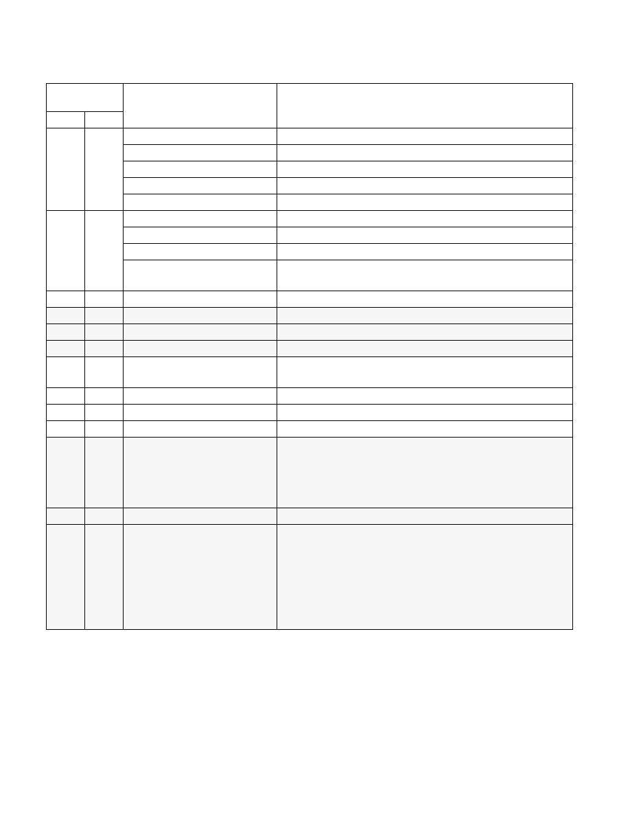
Table 35-46. MSRs in the P6 Family Processors (Contd.)
Register
Address
Register Name
Bit Description
Hex
Dec