Vol. 2A 2-15
INSTRUCTION FORMAT
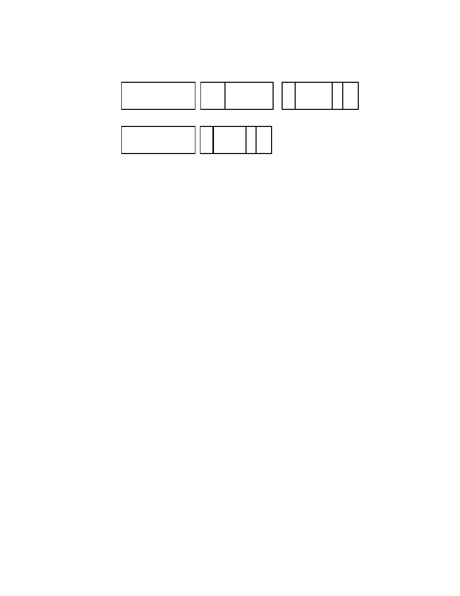
Figure 2-9. VEX bit fields
The following subsections describe the various fields in two or three-byte VEX prefix.
2.3.5.1
VEX Byte 0, bits[7:0]
VEX Byte 0, bits [7:0] must contain the value 11000101b (C5h) or 11000100b (C4h). The 3-byte VEX uses the C4h
first byte, while the 2-byte VEX uses the C5h first byte.
2.3.5.2
VEX Byte 1, bit [7] - ‘R’
VEX Byte 1, bit [7] contains a bit analogous to a bit inverted REX.R. In protected and compatibility modes the bit
must be set to ‘1’ otherwise the instruction is LES or LDS.
11000100
1
6
7
0
vvvv
1 0
3
2
L
7
R: REX.R in 1’s complement (inverted) form
00000: Reserved for future use (will #UD)
00001: implied 0F leading opcode byte
00010: implied 0F 38 leading opcode bytes
00011: implied 0F 3A leading opcode bytes
00100-11111: Reserved for future use (will #UD)
Byte 0
Byte 2
(Bit Position)
vvvv: a register specifier (in 1’s complement form) or 1111 if unused.
6
7
0
R X B
Byte 1
pp:
opcode extension providing equivalent functionality of a SIMD prefix
W: opcode specific (use like REX.W, or used for opcode
m-mmmm
5
m-mmmm:
W
L: Vector Length
0: Same as REX.R=1 (64-bit mode only)
1: Same as REX.R=0 (must be 1 in 32-bit mode)
4
pp
3-byte VEX
11000101
1
6
7
0
vvvv
1 0
3
2
L
7
R
pp
2-byte VEX
B: REX.B in 1’s complement (inverted) form
0: Same as REX.B=1 (64-bit mode only)
1: Same as REX.B=0 (Ignored in 32-bit mode).
extension, or ignored, depending on the opcode byte)
0: scalar or 128-bit vector
1: 256-bit vector
00: None
01: 66
10: F3
11: F2
0: Same as REX.X=1 (64-bit mode only)
1: Same as REX.X=0 (must be 1 in 32-bit mode)
X: REX.X in 1’s complement (inverted) form