15-2 Vol. 1
PROGRAMMING WITH INTEL® AVX-512
15.1.4
Instruction Syntax Enhancement
The architecture of EVEX encoding enhances the vector instruction encoding scheme in the following way:
•
512-bit vector-length, up to 32 ZMM registers, and enhanced vector programming environment are supported
using the enhanced VEX (EVEX).
The EVEX prefix provides more encodable bit fields than the VEX prefix. In addition to encoding 32 ZMM registers
in 64-bit mode, instruction encoding using the EVEX prefix can directly encode 7 (out of 8) opmask register oper-
ands to provide conditional processing in vector instruction programming. The enhanced vector programming envi-
ronment can be explicitly expressed in the instruction syntax to include the following elements:
•
An opmask operand: the opmask registers are expressed using the notation “k1” through “k7”. An EVEX-
encoded instruction supporting conditional vector operation using the opmask register k1 is expressed by
attaching the notation {k1} next to the destination operand. The use of this feature is optional for most instruc-
tions. There are two types of masking (merging and zeroing) differentiated using the EVEX.z bit ({z} in
instruction signature).
•
Embedded broadcast may be supported for some instructions on the source operand that can be encoded as a
memory vector. Data elements of a memory vector may be conditionally fetched or written to.
•
For instruction syntax that operates only on floating-point data in SIMD registers with rounding semantics, the
EVEX encoding can provide explicit rounding control within the EVEX bit fields at either scalar or 512-bit vector
length.
In AVX-512 instructions, vector addition of all elements of the source operands can be expressed in the same
syntax as AVX instruction:
VADDPS zmm1, zmm2, zmm3
Additionally, the EVEX encoding scheme of AVX-512 Foundation can express conditional vector addition as:
VADDPS zmm1 {k1}{z}, zmm2, zmm3
where:
•
Conditional processing and updates to destination are expressed with an opmask register.
•
Zeroing behavior of the opmask selected destination element is expressed by the {z} modifier (with merging
as the default if no modifier is specified).
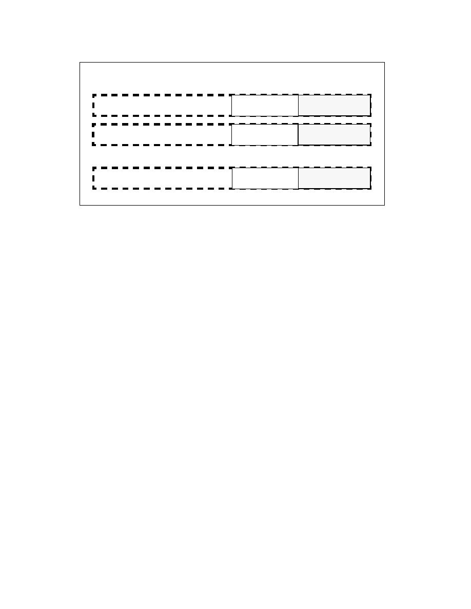
Figure 15-1. 512-Bit Wide Vectors and SIMD Register Set
. . .
XMM31
ZMM31
Bit#
0
255
256
511
YMM31
127
128
XMM1
ZMM1
YMM1
XMM0
ZMM0
YMM0