10-4 Vol. 1
PROGRAMMING WITH INTEL® STREAMING SIMD EXTENSIONS (INTEL® SSE)
•
flush-to-zero flag that provides a means of controlling underflow conditions on SIMD floating-point operations
•
denormals-are-zeros flag that controls how SIMD floating-point instructions handle denormal source operands
The contents of this register can be loaded from memory with the LDMXCSR and FXRSTOR instructions and stored
in memory with STMXCSR and FXSAVE.
Bits 16 through 31 of the MXCSR register are reserved and are cleared on a power-up or reset of the processor;
attempting to write a non-zero value to these bits, using either the FXRSTOR or LDMXCSR instructions, will result
in a general-protection exception (#GP) being generated.
10.2.3.1 SIMD Floating-Point Mask and Flag Bits
Bits 0 through 5 of the MXCSR register indicate whether a SIMD floating-point exception has been detected. They
are “sticky” flags. That is, after a flag is set, it remains set until explicitly cleared. To clear these flags, use the
LDMXCSR or the FXRSTOR instruction to write zeroes to them.
Bits 7 through 12 provide individual mask bits for the SIMD floating-point exceptions. An exception type is masked
if the corresponding mask bit is set, and it is unmasked if the bit is clear. These mask bits are set upon a power-up
or reset. This causes all SIMD floating-point exceptions to be initially masked.
If LDMXCSR or FXRSTOR clears a mask bit and sets the corresponding exception flag bit, a SIMD floating-point
exception will not be generated as a result of this change. The unmasked exception will be generated only upon the
execution of the next SSE/SSE2/SSE3 instruction that detects the unmasked exception condition.
For more information about the use of the SIMD floating-point exception mask and flag bits, see Section 11.5,
“SSE, SSE2, and SSE3 Exceptions,” and Section 12.8, “SSE3/SSSE3 And SSE4 Exceptions.”
10.2.3.2 SIMD Floating-Point Rounding Control Field
Bits 13 and 14 of the MXCSR register (the rounding control [RC] field) control how the results of SIMD floating-point
instructions are rounded. See Section 4.8.4, “Rounding,” for a description of the function and encoding of the
rounding control bits.
10.2.3.3 Flush-To-Zero
Bit 15 (FZ) of the MXCSR register enables the flush-to-zero mode, which controls the masked response to a SIMD
floating-point underflow condition. When the underflow exception is masked and the flush-to-zero mode is
enabled, the processor performs the following operations when it detects a floating-point underflow condition:
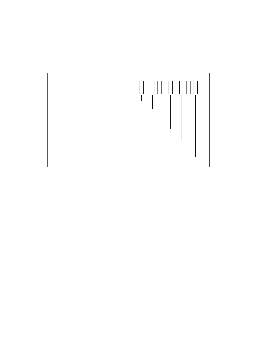
Figure 10-3. MXCSR Control/Status Register
31
16
Overflow Mask
Divide-by-Zero Mask
Denormal Operation Mask
Invalid Operation Mask
Denormals Are Zeros*
Precision Flag
Underflow Flag
Underflow Mask
Flush to Zero
Rounding Control
15
13
14
12 11 10 9 8 7 6 5 4 3 2 1 0
Precision Mask
Overflow Flag
Divide-by-Zero Flag
Denormal Flag
Invalid Operation Flag
F
Z
R
C
P
M
Z
E
O
E
U
E
P
E
I
M
D
M
Z
M
O
M
U
M
Reserved
D
E E
I
D
A
Z
* The denormals-are-zeros flag was introduced in the Pentium 4 and Intel Xeon processor.